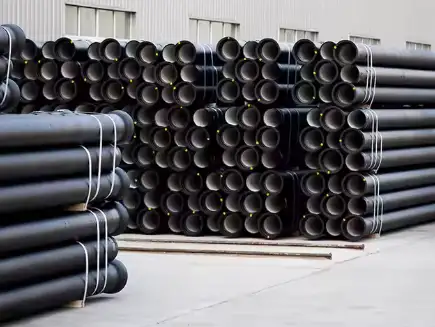
Roughness coefficients quantify the internal surface texture of pipes and determine frictional head losses in fluid flow calculations. For ductile iron pipes—widely used in water distribution and industrial systems—the most common parameters are:
-
Absolute roughness (e) for the Darcy–Weisbach equation, expressed in mm or ft.
-
Hazen–Williams C factor, an empirical coefficient for water flow in closed conduits.
-
Manning’s n, traditionally used for open-channel flow but sometimes applied to full-pipe calculations.

Understanding Roughness Coefficients
Darcy–Weisbach Absolute Roughness
The Darcy–Weisbach equation uses an absolute roughness (e) value—the average height of surface irregularities—to compute the friction factor. For new ductile iron pipes, e is typically 0.061 mm (0.0002 ft) . Over decades in service, internal corrosion deposits and biofilm can increase e to up to 3 mm in poorly maintained systems.
Hazen–Williams C Factor
The Hazen–Williams formula, favored for municipal water supply networks, relates head loss to flow rate via the C factor, where higher values indicate smoother pipe walls. Typical C values for ductile iron include:
-
Unlined (new): 140
-
Cement-lined (new): 120
Evidence shows a 10–15% decline in C over time as internal roughness develops, potentially reducing C from 140 to around 120 after several decades.
Manning’s n Coefficient
Although primarily for open-channel hydraulics, Manning’s n is sometimes used for full-pipe flow, especially in sewer design. For cast or ductile iron, n typically ranges 0.011–0.013 for new pipes.
Typical Values for Ductile Iron Pipes
| Coefficient Type | Parameter | Typical Value | Typical Range |
|---|---|---|---|
| Absolute Roughness (e) | mm (ft) | 0.061 mm (0.0002 ft) | 0.061 mm – 3 mm |
| Hazen–Williams C Factor | — | 140 (unlined) | 120 – 140 |
| Manning’s n | — | 0.012 | 0.009 – 0.016 |
Factors Affecting Roughness in Ductile Iron Pipes
-
Cement Lining Condition
-
Intact cement linings maintain lower roughness; deterioration leads to increased head loss.
-
-
Corrosion and Scaling
-
Iron oxide deposits raise absolute roughness significantly over time.
-
-
Biofilm and Slime
-
Microbial growth can narrow flow paths and elevate friction factors.
-
-
Cleaning and Maintenance
-
Periodic flushing reduces buildup and helps sustain design C and n values.
-
Design Considerations and Applications
-
Pressurized Systems: Use the Darcy–Weisbach equation with e values for detailed head-loss calculations in water distribution mains.
-
Municipal Networks: The Hazen–Williams formula simplifies design but requires attention to C-value declines over pipe life.
-
Sewer and Stormwater: While Manning’s n is common for partially full pipes, practitioners should verify n against local rehabilitation standards.
FAQ
Q1: What is the absolute roughness of new ductile iron pipe?
A: New ductile iron pipelines typically exhibit an absolute roughness e of 0.061 mm (0.0002 ft) .
Q2: How does cement lining affect the Hazen–Williams C factor?
A: Cement-lined ductile iron pipes usually start with a C of 120, compared to 140 for unlined pipes; lining deterioration can further reduce C over time.
Q3: Which coefficient is recommended for Darcy–Weisbach calculations?
A: The absolute roughness (e) value—0.061 mm for new ductile iron—is used to compute the friction factor in the Darcy–Weisbach formula.
Q4: How does roughness change over the service life of ductile iron?
A: Corrosion, scaling, and biofilm can raise e from 0.061 mm up to 3 mm and lower Hazen–Williams C by 10–15% over several decades.
Q5: Can Manning’s n be applied to closed conduits?
A: While designed for open channels, Manning’s n (≈0.012) is sometimes used for full-pipe sewer design but should be validated against empirical studies.
References:
- Darcy–Weisbach Equation – Wikipedia
- Hazen–Williams Equation and Coefficients – American Water Works Association (AWWA)
- Manning’s Equation and Roughness Coefficients – U.S. Bureau of Reclamation
- Pipe Roughness, Aging, and Cleaning Effects – Water Research Foundation
- EPA Guidelines on Corrosion and Roughness in Water Distribution Systems – U.S. Environmental Protection Agency
