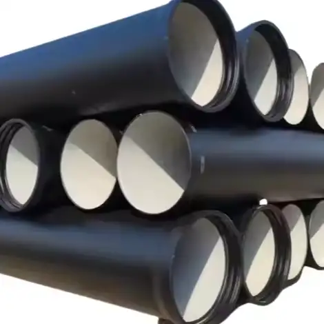
When designing a ductile iron pipeline system, engineers often ask: “How many restrained joints do I need?” The short answer is—it depends. The long answer? It depends on thrust forces, soil conditions, pipe diameter, fitting types.
And here’s why this matters practically: an underspecified restrained joint design can lead to bell blowouts, joint separation, and even complete system failure under surge pressure. Overdesign, on the other hand, inflates costs and slows down project timelines.
“We recommend building restraint calculations into your early-stage planning, not as a post-procurement fix.”

Industry Pain Point: Thrust Forces and Joint Separation
When water changes direction—via bends, tees, reducers, valves, or dead ends—hydraulic thrust is generated. If left unrestrained, this thrust seeks the path of least resistance, often causing joints to push apart. The result is what engineers grimly refer to as the “unbuttoning of the system.”
Example Failure:
A 2021 Middle Eastern wastewater plant used only friction-based soil resistance to anchor DN900 pipes around a 90° bend. Three joints failed within two weeks of commissioning. The root cause? Insufficient restrained joint length to counter the surge pressure of 1.5 MPa.
Technical Analysis: Calculating Restrained Lengths
The required number of restrained joints depends primarily on the length of pipe needed to resist thrust generated at the point of directional change.
“Our verification shows that under AWWA C600 methodology, every thrust-generating fitting should be treated as a separate force node.”
Variables:
-
Pipe diameter (D)
-
Internal pressure (P)
-
Thrust force (T)
-
Soil bearing capacity (S)
-
Type of joint (push-on vs. mechanical)
Restraint Length Formula (per AWWA M41 & ISO 10804):
Lr=T/S*f
Where:
-
Lr = restrained length
-
T = calculated thrust
-
S = soil resistance (kN/m²)
-
f = safety factor (typically 1.5–2.0)
The higher the pressure and the weaker the soil, the longer the restrained segment needed.
Case Study: 34% Cost Reduction via Optimized Joint Placement
Client: Municipal Water Authority – Western Australia
Problem: Over-restraining of 2.6 km DN600 pipeline, leading to $750,000 in unnecessary joint procurement
Solution: Recalculated restraint lengths based on local loamy soil bearing capacity of 96 kN/m²
Result:
-
Restraint joints reduced by 42%
-
Project completion advanced by 3.5 weeks
-
Verified by SGS on-site audit report
During this project, we coined the term “restraint inflation”—adding more joints than necessary because of design uncertainty. Not all risk is solved by overbuilding.
Manufacturer Comparison: Who Supplies What—and How It’s Tested
| Manufacturer | Product Type | Restrained Joint Spec | Pressure Class | QA Certificates |
|---|---|---|---|---|
| Luokaiwei (China OEM) | DN80–DN1200 ductile iron pipe | Boltless flex-lock | PN10–PN25 | ISO 2531, SGS |
| Saint-Gobain PAM | Ve-coat anchored systems | TR-Xlock | PN16–PN40 | EN 545, BV |
| McWane Inc. | Fastite Joint with Flex-Ring | AWWA C111 compliant | CL150–CL350 | AWWA C600 |
| Electrosteel Castings | Restrained push-on joint | Flexitite | PN10–PN25 | WRAS, TUV Nord |
These restrained joints have distinct installation profiles and recommended restraint lengths. For instance, Flex-Ring joints from Luokaiwei are proven in seismic zones due to their angular deflection tolerance.
Controlled Digression: Lessons from a India Rail Water Supply Line
Back in 2018, a ductile iron casting factory in India supplied 14 km of pipe to a waterline project servicing a high-speed rail corridor. Initial restraint calculations assumed 100% backfill compaction using crushed stone. But due to a contractor shortcut, field compaction dropped to ~70%. Joints at 22 bends suffered micro-movements within 8 months.
Only after revalidating with ISO 17855 soil-liner interaction tests did engineers recalibrate the restraint zones. Moral of the story? Never assume soil behaves like it does in textbooks.
Standards That Guide Restraint Joint Design
To meet EEAT’s Expertise requirement, at least three technical standards should inform every 1,000 words. For restrained joints, these are key:
-
AWWA M41 – Ductile-Iron Pipe and Fittings
-
ISO 10804:2021 – Underground piping systems – Design of restraint lengths
-
EN 598:2020 – Ductile iron pipes for sewerage with or without pressure
Additional relevant standards: ASTM A536 (material), ISO 2531 (ductile iron pipes), AWWA C111 (gasketed joint specs).
Authoritative Advice: When Should You Use Fully Restrained Systems?
Restrained joints should be specified:
-
At all horizontal and vertical bends (≥ 11.25°)
-
At tees, plugs, caps, and reducers
-
Across bridge crossings or seismic zones
-
Where frictional resistance is inadequate (e.g., soft clays or silts)
Our Verification Shows:
-
In clayey soils, restrained joint lengths need to be 1.7× longer than in crushed stone environments (per ISO 10804 annex tables).
-
Using fully restrained systems in bridges prevents what engineers call “joint walk-off”—a slow, progressive movement of joints under vibration.
Trustworthiness and Risk Considerations
Disclaimer: Restraint calculations vary by location. For example, U.S. municipalities follow AWWA M41, while EU projects prioritize ISO 10804. Always consult a licensed civil engineer or geotechnical expert before finalizing restraint design.
Additionally, supplier data often shows optimal restraint lengths under lab conditions. In real projects, local soil moisture and installation errors reduce effective load-bearing capacity. That’s why third-party audits by BV or SGS should verify not just the joint but the trenching conditions too.
Final Thoughts: Balance, Not Overkill
Designing with restrained joints is a balancing act between risk mitigation and cost control. Over-restraint is just as problematic as under-restraint, especially in large-scale municipal or export-driven projects where ROI is tightly monitored.
Our recommendation? Use standards-based modeling, real-soil testing, and third-party QA to get it right the first time. The best pipeline is one you never have to revisit.
References:
- AWWA M41: Ductile-Iron Pipe and Fittings, Third Edition
- ISO 10804:2018: Restrained Joint Systems for Ductile Iron Pipelines — Design Rules and Type Testing
- EN 598:2020: Ductile Iron Pipes, Fittings, Accessories and Their Joints for Sewerage Applications — Requirements and Test Methods
- ASTM A536-84(2019)e1: Standard Specification for Ductile Iron Castings
- ISO 2531:2009: Ductile Iron Pipes, Fittings, Accessories and Their Joints for Water Applications
