Cement-lining significantly enhances the hydraulic performance of ductile iron pipes by raising the Hazen-Williams C-factor to approximately 140–150, minimizing head loss and maximizing flow efficiency. This conclusion guides engineers to specify cement-lined ductile iron pipe for projects requiring superior long-term hydraulic capacity, corrosion resistance, and maintenance reliability.
1. Fundamentals of C-Factor in Hydraulic Design
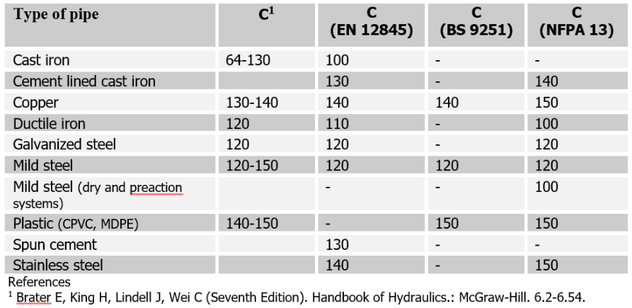
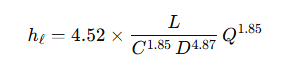
The Hazen-Williams C-factor (or coefficient) is a dimensionless roughness value used in the Hazen-Williams equation to estimate head loss due to friction in pipes conveying water. For a pipe of length L (ft) and diameter D (inches), with flow rate Q (gpm), the head loss hₗ (ft) is:
-
Hazen-Williams C-factor (C): Reflects the internal surface roughness; higher C means smoother surface and less friction.
-
Typical Ranges:
-
Unlined cast iron: C ≈ 100–120
-
Cement-lined ductile iron: C ≈ 140–150
-
New PVC: C ≈ 150
-
1.1 Derivation and Limitations
While empirical and developed over a century ago, Hazen-Williams remains popular for water distribution networks due to simplicity; however, it applies only to clean, full-flow water at ambient temperature. It does not account for changes in viscosity or turbulent regimes outside typical distributions.
1.2 Role of Cement Lining
Cement mortar lining provides:
-
Surface Smoothness: Uniform, dense interior reduces roughness and raises C.
-
Corrosion Protection: Barrier against corrosive agents preserves roughness over decades.
-
Scale Resistance: Limits tuberculation and deposit formation.
1.3 Comparison with Other Roughness Models
| Model | Governing Equation | Advantages | Disadvantages |
|---|---|---|---|
| Hazen-Williams | hₗ ∝ Q¹․⁸⁵/(C¹․⁸⁵·D⁴․⁸⁷) | Simple, widely accepted | Water only; empirical; limited T, ν |
| Darcy-Weisbach | hₗ = f·(L/D)·(v²/2g) | Physically based; accommodates fluids | Requires Moody chart or f iteration |
| Manning-Strickler | V = (1.49/n)·R²ᐟ³·S¹ᐟ² | Good for open channel and pressurized | Less common for water mains |
Note: Engineers must choose the model suited for fluid properties, required accuracy, and available data.
2. Manufacturing and Application of Cement-Lined Ductile Iron Pipe
Ductile iron pipe (DIP) with cement mortar lining combines a core of spheroidal graphite iron with an interior coating of Portland cement mortar. Typical standards include AWWA C104/A21.4.
2.1 Base Pipe Production
-
Material: ASTM A536 Grade 60-42-10 ductile iron:
-
Tensile strength ≥ 60 ksi
-
Elongation ≥ 10 %
-
-
Forming: Centrifugal casting produces uniform thickness.
-
Annealing: Stress relief to improve ductility.
2.2 Cement Lining Process
-
Pre-preparation: Internal surface cleaned and pre-wetted.
-
Mortar Application: Dry or wet-mortar spray; thickness typically 0.01 × pipe diameter, minimum 0.08 in.
-
Curing: Steam curing under controlled humidity for 24 h.
-
Quality Control: Holiday testing; lining thickness gauges.
2.3 Typical Applications
-
Potable Water Distribution: High C ensures minimal pumping costs.
-
Wastewater Force Mains: Corrosion barrier extends service life.
-
Irrigation Systems: Uniform flow critical in agricultural contexts.
2.4 Service Life and Durability
Concrete mortar lining resists tuberculation, chemical attack, and abrasion. Typical design life exceeds 75 years under normal service conditions.
3. Hydraulic Performance Comparison
Quantifying head loss differences between unlined ductile iron, cement-lined ductile iron, and alternative materials.
3.1 Reference Conditions
-
Pipe Size: 12 in. I.D.
-
Flow Rate: 3,000 gpm
-
Length: 1,000 ft
3.2 Head Loss Calculations
| Pipe Type | C-Factor | Head Loss (ft/1,000 ft) | Percentage Reduction vs. Unlined |
|---|---|---|---|
| Unlined Ductile Iron | 110 | 29.8 | — |
| Cement-Lined Ductile Iron | 145 | 11.5 | 61 % |
| PVC (C=150) | 150 | 10.4 | 65 % |
| HDPE (C=150) | 150 | 10.4 | 65 % |
3.3 Pumping Cost Impacts
Assuming pumping head at 100 ft/million gal and energy cost of $0.10/kWh:
-
Annual Energy Savings:
Cement-lined vs. unlined DIP: ~$12,000 per mile of 12 in. pipe.
4. Factors Influencing C-Factor Over Service Life
While initial C for cement-lined DIP is ~145, factors can reduce performance:
4.1 Interior Scaling and Deposits
-
Microbial Growth: Biofilm formation can add roughness.
-
Mineral Scaling: Hard water deposits; design filtration helps control.
4.2 Corrosion and Tuberculation
-
Corrosive Agents: Chlorides, sulfates in water can attack lining.
-
Cathodic Protection: Applying sacrificial anodes or impressed current systems.
4.3 Mechanical Damage
-
Debris Impact: Abrasive particles can erode lining.
-
Cleaning Operations: Aggressive pigging may damage mortar.
4.4 Inspection and Reconditioning
-
In-Line Inspection (ILI): Sonar or video to measure deposit thickness.
-
Re–Lining Methods: Slip-lining, cured-in-place pipe (CIPP), or spot mortar repairs.
5. Design Considerations and Standards
5.1 Governing Standards
-
AWWA C104/A21.4: Cement mortar lining requirements.
-
ISO 4179: Internal lining of ductile iron pipes.
-
EN 545: Ductile iron pipes with cement mortar lining for water pipelines.
5.2 Specifying C-Factor in Models
In modeling software (e.g., EPANET, WaterGEMS):
-
Initial C: 145–150 for cement-lined DIP.
-
Adjustment: Apply aging coefficients (e.g., –2 per decade).
5.3 Lifecycle Cost Analysis
Accounting for:
-
Capital Cost: Slight premium (~5 %) over unlined DIP.
-
Operational Cost: Energy savings through reduced friction.
-
Maintenance Cost: Lower frequency of relining.
5.4 Sustainability and Green Design
Cement-lined DIP offers:
-
Recyclability: Iron pipe is 100 % recyclable.
-
Longevity: Reduces environmental impact of replacements.
-
Energy Efficiency: Lower pumping requirements.
6. Installation and Quality Assurance
6.1 Handling and Storage
-
Packaging: Wrapped segments to protect lining.
-
On-Site Storage: Sheltered, elevated to avoid moisture pooling.
6.2 Trenching and Bedding
-
Trench Design: Appropriate width and bedding material (sand or gravel).
-
Embedment: Even support to prevent point loads.
6.3 Joint Assembly
-
Mechanical Joints: Gaskets compatible with cement lining.
-
Flanged Joints: Ensure face flatness; avoid gasket embedment damage.
6.4 Post-Installation Testing
-
Hydrostatic Test: Pressure at 1.5 × design pressure.
-
Inspection for Lining Damage: Visual and holiday testing.
6.5 Documentation and Certification
-
Mill Test Reports: Chemical and mechanical properties.
-
Lining Certificates: Thickness and adhesion.
Frequently Asked Questions (FAQs)
Q1. What is the typical Hazen-Williams C-factor for cement-lined ductile iron pipe?
The industry standard Hazen-Williams C-factor for new cement-lined ductile iron pipe is typically specified between 140 and 150. This elevated C-factor reflects the smooth, dense surface of the cement mortar lining, which significantly reduces internal friction compared to unlined or bare iron. Over time, deposition of scale or biofilm can lower the effective C-factor; engineers often account for aging by reducing the initial value by 1 to 2 points per decade of service. Selecting the correct initial C-factor in hydraulic models ensures accurate prediction of head loss, pump sizing, and energy consumption throughout the pipe’s lifecycle. Continuous monitoring and occasional reconditioning help maintain performance close to the original design assumptions.
Q2. How does cement lining improve the service life of ductile iron pipe?
Cement mortar lining provides both hydraulic and corrosion-protection benefits, extending ductile iron pipe life beyond 75 years in typical water distribution service. The lining acts as a physical barrier, preventing direct contact between the pipe’s metal surface and corrosive constituents—such as chlorides, sulfates, or aggressive soils—that would otherwise initiate pitting or tuberculation. Moreover, the smooth interior surface minimizes roughness-related wear and reduces deposit adhesion; this collectively limits abrasive erosion from particulate-laden flows. Institutional standards (e.g., AWWA C104) mandate quality control measures—holiday detection, thickness gauging, and adhesion tests—to ensure lining integrity. Field experience demonstrates that properly installed and cured cement linings maintain hydraulic efficiency and structural protection far longer than unlined alternatives, thereby lowering whole-life maintenance and replacement costs.
Q3. Can the Hazen-Williams equation be used for fluids other than water?
The Hazen-Williams formula was empirically derived for water at typical ambient temperatures and flow regimes found in municipal distribution systems. It assumes a constant kinematic viscosity and neglects temperature dependence; thus, applying it to fluids with significantly different viscosity—such as oils, slurries, or wastewater with high solids content—introduces substantial errors. For non-Newtonian or temperature-sensitive liquids, engineers should employ the Darcy-Weisbach equation, which uses a friction factor (f) obtained from the Moody chart or computational methods that account for Reynolds number and relative roughness. Some specialized water-treatment scenarios involving chemical additives may still use Hazen-Williams if viscosity changes are minor; however, verification through pilot testing or comparison with more rigorous models is strongly recommended to ensure hydraulic predictions remain within acceptable accuracy.
Q4. How do I maintain the C-factor of in-service cement-lined pipes?
Maintaining the C-factor requires preventing and controlling internal deposits, corrosion, and mechanical damage. A proactive maintenance program includes: scheduled flushing to remove sediment and debris; periodic pigging with soft cleaning pigs that will not abrade the mortar; water quality management to reduce hardness and microbial growth; and monitoring via in-line inspection tools (sonar, video) to quantify deposit thickness. If localized damage or deposition is detected, spot reconditioning using cement grout or epoxy mortar may restore the surface. Cathodic protection systems alleviate stray current corrosion that could undermine the lining. Finally, training of operations personnel on proper pigging practices and chemical dosing ensures maintenance activities support, rather than degrade, the lining’s smoothness and overall C-factor.
Q5. What factors determine whether to choose cement-lined DIP over PVC or HDPE?
Selection depends on project-specific criteria:
-
Hydraulic Requirements: Although PVC and HDPE feature C-factors of ~150, cement-lined DIP offers comparable smoothness with higher pressure ratings (up to 350 psi) and superior surge resistance.
-
Structural Strength: Ductile iron pipes withstand higher external loads, making them suitable for deep installations or heavy traffic areas.
-
Corrosion Environment: DIP with cement lining resists aggressive soils better than plastic, reducing potential for stress-cracking or deformation.
-
Lifecycle Cost: While plastic pipes may have lower initial cost, cement-lined DIP’s durability, reparability, and recyclability often yield a lower net present value over 75+ years.
-
Regulatory Standards: Certain municipal codes mandate ductile iron for critical services (e.g., raw water mains), influencing material choice.
Engineers should perform a multi-criteria analysis—including capital, operational, and environmental costs—to select the optimum pipe material.
Q6. How do aging and deposits affect the long-term accuracy of hydraulic models?
Hydraulic models assume steady C-factors to calculate head loss. However, over decades, biofilms, mineral scaling, and corrosion products accumulate, effectively reducing the true C-factor below its initial design value. For cement-lined DIP, empirical studies suggest a decay rate of 1–2 C points per 10 years in well-maintained systems; poorly maintained lines may see faster declines. To maintain model accuracy, engineers should: schedule periodic flow monitoring and validation tests; update C-factors based on in-field measurements; apply conservative default reductions for aging; and incorporate deposit thickness data from in-line inspection. Without such adjustments, pump energy estimates, pressure predictions, and service-level assessments can be overly optimistic, leading to under-sized infrastructure and increased operational risks.
References:
1. AWWA C104/A21.4 – Cement–Mortar Lining for Ductile-Iron Pipe and Fittings for Water
3. U.S. EPA – Water Infrastructure: Understanding Pipe Materials
