Replacing a cast ductile iron flap check valve promptly restores system integrity, prevents backflow, and extends equipment lifespan. This guide delivers authoritative, step-by-step solutions grounded in industry best practices, ensuring seamless valve replacement and sustained operational performance.
1. Detailed Overview of Cast Ductile Iron Flap Check Valves
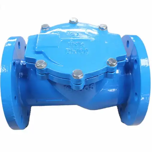
Cast ductile iron flap check valves, also known as swing check valves, are unidirectional devices designed to allow fluid flow in one direction and prevent reverse flow. Constructed from spheroidal graphite iron, these valves combine the corrosion resistance of cast iron with enhanced strength and ductility. Primarily installed in pipelines for water treatment, sewage, oil and gas, and industrial process systems, they safeguard pumps and equipment by automatically closing when flow reverses or pressure drops.
Ductile iron’s unique microstructure—nodular graphite in a ferritic matrix—gives these valves high tensile strength (up to 65,000 psi) and significant impact resistance. Flap check valves feature a hinged disc or “flap” that swings against a seat under reverse flow conditions, creating a tight seal. Compared to lift check valves, flap check variants generate lower pressure drops due to streamlined fluid passage when fully open, and they respond rapidly to flow reversal, minimizing water hammer and pipeline stress.
Key components include the valve body, hinge pin or shaft, flap disc, seat ring, and gaskets or O‑rings. Body designs range from single flanged to wafer and lugged styles, accommodating ANSI, DIN, or ISO standards. Seat materials may vary—epoxy coatings, stainless steel inserts, or elastomeric seals—to match fluid chemistry and temperature requirements. Ductile iron flap check valves typically operate within pressure ratings of PN10 to PN40 (150–600 psi) and temperature ranges from 20 °C to 200 °C, though specialty alloys extend these limits.
Integration into piping systems demands alignment accuracy, flange compatibility, and proper support to avoid undue hinge stress. The choice of flange drilling (ANSI B16.1/B16.5 or EN1092‑2) and gasket type (spiral wound, ring joint, or rubber) influences sealing efficacy. Advanced models incorporate soft‑seated or metal‑seated designs for abrasive or high‑temperature service. Overall, the combination of ductile iron’s mechanical properties and flap check geometry ensures reliable backflow prevention in diverse applications.
2. Common Failure Modes and Indicators for Replacement
Understanding the mechanisms that lead to cast ductile iron flap check valve degradation is essential for timely replacement. Key failure modes include:
- Corrosion and Erosion: Prolonged exposure to aggressive fluids or suspended solids causes pitting, wall thinning, and seat damage. Acidic or chlorinated media accelerate corrosion of the ductile iron body, while high‑velocity flow with particulates contributes to erosive wear on the flap disc and seat, compromising sealing integrity.
- Hinge Pin Fatigue: Repeated cycling under fluctuating pressures induces metal fatigue in the hinge pin or shaft, potentially leading to cracking or breakage. Misalignment or improper lubrication exacerbates wear on pivot points, increasing the risk of hinge failure and uncontrolled disc movement.
- Seal Degradation: Elastomeric seals, gaskets, and O‑rings lose elasticity over time, especially under thermal cycling or chemical attack. Hardening, cracking, or extrusion of seals creates leakage paths and reduces the valve’s backflow prevention capability.
- Mechanical Wear and Misalignment: Solid particles or debris can obstruct flap seating surfaces, causing incomplete closure. Additionally, bolt torque loss or flange misalignment can distort the valve body, leading to binding of the flap and uneven wear.
- Thermal Stress Cracking: Rapid temperature changes—such as cold water slugging against a hot valve—generate thermal gradients that produce stress fractures in the ductile iron or coating layers, impacting structural integrity.
Indicators of impending failure often manifest as:
- Audible Noise: Rattling, banging, or fluttering during flow reversal suggests loose hinge components or worn seating surfaces.
- Leakage and Weeping: Continuous drip or seepage past the seat indicates seal compromise or surface degradation.
- Pressure Loss: Unexpected pressure drops in the system point to internal leakage or partial flap obstruction.
- Operational Delays: Sluggish valve response or incomplete opening at startup reveals hinge binding or corrosion buildup.
Timely detection through routine visual inspections, non‑destructive testing (NDT), and flow performance monitoring prevents catastrophic failures. Techniques such as ultrasonic thickness gauging, magnetic particle inspection, and endoscopic examination within the valve body facilitate proactive maintenance decisions. When wear exceeds defined thresholds—such as >10% wall thinning or hinge pin run‑out beyond tolerance—replacement is mandated to maintain system safety and efficiency.
3. Step‑by‑Step Replacement Procedure
Performing a cast ductile iron flap check valve replacement demands meticulous planning and adherence to safety protocols. The following procedural outline ensures a successful intervention:
1. Pre‑Replacement Preparation
- System Assessment: Review P&IDs (piping and instrumentation diagrams) to confirm valve location, orientation, and service conditions. Identify isolation points—such as block valves upstream and downstream—to isolate the valve from pressure and flow.
- Personal Protective Equipment (PPE): Equip personnel with safety glasses, gloves resistant to local fluid chemistry, and hearing protection. For confined spaces or hazardous fluids, supply respirators and chemical‑resistant suits.
- Tools and Materials: Assemble torque wrenches, flange spreaders, lifting slings, replacement valve, gaskets, flange bolts with nuts and washers, thread‑locking compounds, and appropriate lubricants. Verify that replacement valve meets or exceeds original specifications (pressure rating, flange drilling, seat material).
2. System Shutdown and Isolation
- Close upstream and downstream block valves.
- Drain the pipeline segment by opening drain valves or bleed points until fluid flow ceases and pressure equalizes to ambient.
- Tag and lock out isolation valves to prevent inadvertent activation.
3. Removing the Existing Valve
- Loosen flange bolts in a star or cross pattern to minimize flange distortion.
- Use flange spreaders to relieve bolt load and separate flanges without damaging sealing faces.
- Employ lifting equipment—chain hoist or crane—to support valve weight and prevent sudden flange separation.
- Extract the valve carefully, avoiding damage to mating flanges or adjacent piping.
4. Inspection and Preparation of Flanges
- Clean flange faces with non‑metallic scrapers and solvent to remove old gasket residue, corrosion, and debris.
- Inspect face finish and flatness using straightedge and feeler gauges; field machine faces if deviation exceeds 0.05 mm.
- Verify bolt hole alignment and dimensional tolerances according to ISO 5752 or ASME B16.5 standards.
5. Installing the Replacement Valve
- Position new valve between flanges, ensuring correct flow direction arrow alignment.
- Insert new gaskets—spiral wound recommended for high‑pressure service—and align bolt holes.
- Hand‑tighten flange bolts with washers and nuts. Ensure protrusion beyond nut does not exceed twice bolt diameter.
- Apply thread‑locking compound on bolt threads if vibration or cyclic loading is anticipated.
6. Torque and Leak Testing
- Tighten bolts in a progressive, star pattern to the torque values specified by the valve manufacturer (e.g., 150 ft·lb for M16 bolts on PN25 flanges).
- Conduct hydrostatic testing: pressurize the isolated segment to 1.5× operating pressure and hold for 5 minutes. Inspect all joints for leaks using soap solution or ultrasonic leak detectors.
- Bleed trapped air via vent ports to prevent air pockets that can impede flap movement.
7. Commissioning and Documentation
- Reopen upstream and downstream block valves slowly to prevent water hammer. Monitor pressure gauges for stability.
- Record torque values, test pressures, and any deviations in maintenance logs.
- Update asset management systems with replacement date, part numbers, and next inspection interval.
This systematic approach minimizes downtime and ensures that the new cast ductile iron flap check valve operates within designed parameters, maintaining system reliability and safety.
4. Selection Criteria for Replacement Valves
Selecting an appropriate replacement for a cast ductile iron flap check valve involves balancing performance requirements, material compatibility, and economic considerations. The following factors should be evaluated:
a. Pressure and Temperature Ratings
Ensure the valve’s nominal pressure (PN) and temperature class match or exceed the service conditions. Ductile iron flap check valves are commonly rated PN10 (150 psi) to PN40 (600 psi) and handle temperatures from 20 °C to 200 °C. For higher temperatures or severe services, consider stainless steel or special alloy valves.
b. Material Compatibility
Analyze the fluid’s chemical properties—pH, chlorine content, suspended solids—to determine suitable body and seal materials. Standard ductile iron resists moderate corrosion; however, aggressive media necessitate protective linings (epoxy, rubber) or alternate alloys. Seat materials range from nitrile rubber (20 °C–80 °C) to Viton (20 °C–200 °C).
c. End Connection Style
Match existing piping: flange drilling per ANSI B16.5 or EN1092, wafer-style for compact installations, or lug-style for dead-end service. Wafer valves offer space savings but lack full bolting integrity when under differential pressure.
d. Flow Characteristics
Assess flow coefficient (Cv) and pressure drop. Flap check designs typically yield lower ΔP when fully open but may induce turbulence near the seat. Use manufacturer flow curves to confirm acceptable head loss at design flow rates.
e. Certification and Standards Compliance
Prioritize valves certified to ISO 5208 (shell and seat tightness), API 594 (check valves), and local regulations (e.g., WRAS for potable water in the UK). Quality assurance via third‑party testing (e.g., Lloyd’s Register) enhances reliability for critical applications.
f. Maintenance Accessibility
Opt for designs with removable cover plates or hinge assemblies that facilitate internal inspection without complete pipeline removal. Self‑aligning hinge pins and corrosion‑resistant coatings reduce long‑term maintenance.
g. Lifecycle Cost Analysis
Compare initial purchase price, installation labor, maintenance intervals, and expected service life. Although ductile iron valves may cost slightly more than cast iron, their extended durability and reduced failure rates often yield lower total cost of ownership.
By systematically evaluating these criteria, engineers and maintenance planners can select a replacement valve that aligns with operational goals, regulatory requirements, and budget constraints.
5. Comparative Analysis Tables
To facilitate informed decision‑making, the following tables provide detailed comparisons between cast iron and ductile iron flap check valves, various seat materials, and end connections.
Table 1: Material Comparison
| Property | Cast Iron Flap Check Valve | Ductile Iron Flap Check Valve | Stainless Steel Flap Check Valve |
|---|---|---|---|
| Tensile Strength (psi) | 25,000–35,000 | 60,000–80,000 | 70,000–90,000 |
| Elongation (%) | 1–3 | 10–20 | 20–40 |
| Impact Resistance | Low | High | High |
| Corrosion Resistance | Moderate | Good | Excellent |
| Cost | Low | Moderate | High |
| Typical Service Temperature | 10 °C to 120 °C | 20 °C to 200 °C | 50 °C to 400 °C |
Table 2: Seat Material Comparison
| Seat Material | Temperature Range | Chemical Resistance | Wear Resistance | Typical Applications |
| Nitrile Rubber | 20 °C to 80 °C | Oils, water, mild chemicals | Moderate | Domestic water, light chemicals |
| EPDM | 40 °C to 120 °C | Hot water, steam, acids | Moderate | HVAC, potable water, acidic media |
| Viton (FKM) | 20 °C to 200 °C | Oils, fuels, chlorinated solvents | High | Oil & gas, chemical processing |
| PTFE | 200 °C to 260 °C | Almost all chemicals | High | Aggressive chemicals, pharma |
Table 3: End Connection Comparison
| Connection Type | Space Requirement | Installation Time | Pressure Rating | Reusability | Typical Use Cases |
| Flanged | High | Moderate | Up to PN40 | Low (gasket replace) | Mainlines, industrial systems |
| Wafer | Low | Low | Up to PN25 | Medium | HVAC, building services |
| Lug | Moderate | Moderate | Up to PN25 | High (dead‑end) | Dead‑end service, isolation |
These tables underscore critical trade‑offs and guide selection to optimize performance, reliability, and cost-effectiveness in various service environments.
6. Maintenance Strategies and Best Practices
A robust maintenance program for cast ductile iron flap check valves prolongs service life and ensures uninterrupted operation. Implement the following strategies:
1. Scheduled Inspections
Establish inspection intervals based on service severity—every 3 months for abrasive or corrosive fluids, annually for clean water systems. Use a structured checklist to document visual signs of corrosion, hinge wear, seal condition, and noise during operation.
2. Preventive Maintenance Tasks
- Seal Replacement: Proactively replace elastomeric seals before hardness testing (shore A) indicates >20% stiffness increase.
- Lubrication: Apply high‑temperature, water‑resistant grease to hinge pins every 6 months or after maintenance shutdowns.
- Coating Repairs: Touch up epoxy or rubber linings at the first sign of blistering or delamination to prevent substrate corrosion.
3. Condition Monitoring
Integrate flow meters and pressure transducers upstream and downstream of the valve to detect abnormal pressure differentials (>10% increase) that signal internal leakage or flap jamming. Implement alarm thresholds in SCADA systems for real‑time alerts.
4. Non‑Destructive Testing (NDT)
Perform ultrasonic thickness measurements on the valve body and disc at defined intervals to track corrosion or erosion rates. Magnetic particle inspection of hinge pins reveals surface cracks before catastrophic failure. Dye penetrant testing of weld joints verifies sealing integrity.
5. Spare Parts Management
Maintain an inventory of critical spares—flap discs, hinge pins, seat rings, gaskets—for rapid field replacement. Use part numbering tied to valve serial numbers in the asset management system to prevent mix‑ups.
6. Training and Documentation
Ensure maintenance teams are trained on valve internals, proper disassembly/assembly techniques, and torque specifications. Provide clear, illustrated procedure manuals and maintain digital records of past replacements, torque logs, and NDT results.
7. Environmental and Safety Compliance
Adhere to local regulations for handling and disposal of hazardous fluids and old valve components. Implement lock‑out/tag‑out (LOTO) procedures during maintenance to protect personnel. Use spill containment and absorbents when draining fluids.
By integrating these practices into a comprehensive maintenance framework, organizations optimize valve reliability, minimize unplanned downtime, and achieve cost savings through targeted preventive interventions.
Q1: What are the advantages of using ductile iron over cast iron for flap check valves?
Ductile iron offers significantly higher tensile strength (up to 80,000 psi) and elongation (10–20%) compared to cast iron (tensile strength 25,000–35,000 psi, elongation 1–3%). Its nodular graphite structure imparts better impact resistance and toughness. In practical terms, ductile iron flap check valves can withstand higher pressures, more severe service conditions, and are less prone to brittle fracture under dynamic loading. Additionally, ductile iron’s enhanced resistance to erosive wear makes it suitable for fluids containing suspended solids. The improved mechanical properties reduce failure rates and extend maintenance intervals, resulting in lower lifecycle costs and greater system reliability.
Q2: How do I determine when a flap check valve needs replacement?
Key indicators include visible corrosion pitting on the seat or disc, wall thinning measured by ultrasonic testing exceeding 10% of nominal thickness, hinge pin play beyond manufacturer’s tolerance, and frequent leakage detected as a continuous drip under static conditions. Operational symptoms such as rattling noises during flow reversal, pressure differential increases greater than 10% of normal, and sluggish disc movement also signal degradation. Regular NDT inspections—ultrasonic thickness gauging and magnetic particle crack detection—combined with performance monitoring (pressure vs. flow data) enable maintenance teams to predict end‑of‑life accurately and schedule replacements proactively, minimizing unplanned downtime.
Q3: Can I retrofit a wafer‑style flap check valve into a lug‑style installation?
Retrofit is possible but requires careful evaluation of flange spacing, bolt pattern alignment, and system pressure demands. Wafer valves sit between flanges and rely on flange bolts for alignment; they are best suited to systems with low differential pressures (up to PN25). Lug‑style valves provide bolt accessibility on each flange and allow downstream piping isolation for maintenance. To retrofit, ensure flange drilling matches, confirm adequate bolt engagement length, and verify that the piping support prevents valve misalignment. Engineering calculations must confirm that the wafer design can withstand the system’s operating loads without distortion or leakage.
Q4: What is the impact of fluid velocity on flap check valve life?
High fluid velocities (>3 m/s) increase erosive wear on the disc edges and seat surfaces, accelerating material loss and creating leakage paths. Turbulent flow can also cause vibration of the flap, leading to fatigue on the hinge pin and possible mechanical failure. To mitigate velocity effects, select valves with hardened seat inserts or erosion‑resistant coatings. Where necessary, install velocity‑reducing piping configurations—such as gradual reducers or flow straighteners—upstream of the valve. Adhering to manufacturer’s recommended maximum velocities preserves valve integrity and extends service intervals.
Q5: Are soft‑seated flap check valves suitable for high‑temperature applications?
Soft‑seated valves use elastomeric materials (EPDM, Viton) that have specific temperature limits—EPDM up to 120 °C, Viton up to 200 °C. For applications exceeding these temperatures, metal‑seated designs (stainless steel or alloy) are more appropriate. Soft seats provide excellent leak tightness and noise dampening but degrade under thermal cycling or exposure to aggressive media. When high‑temperature service is required, choose a valve with a metal seat or PTFE sleeve, and verify performance through high‑temperature seat leakage testing per API 598 or ISO 5208 standards.
Q6: How can I minimize downtime during valve replacement?
Effective strategies include procuring a pre‑assembled replacement valve staged on site, conducting detailed pre‑job planning with P&IDs and checklists, and using quick‐disconnect flange adapters if available. Employ bolt tensioning equipment for rapid, consistent torque application. Scheduling replacement during planned shutdown windows, training teams on the specific valve model, and maintaining critical spares in inventory further reduce intervention time. Where possible, install parallel bypass piping to maintain flow while the primary valve is serviced, eliminating full system shutdown and sustaining operational continuity.
References:
1. ASTM A536 – Standard Specification for Ductile Iron Castings
2. API 594 – Check Valves: Flanged, Lug, Wafer, and Butt-Welding
3. ISO 5208 – Industrial Valves — Pressure Testing of Metallic Valves
