A hydrostatic pressure test is a fundamental quality and safety verification for ductile iron pipe installations. It involves subjecting pipe segments to water pressure well above their normal operating limits to ensure structural integrity, leak-tightness, and adherence to strict industry standards such as ANSI/AWWA C151/A21.51 and ASTM guidelines.
1. Introduction to Hydrostatic Pressure Testing
Ductile iron pipe hydrostatic pressure testing is performed to verify the mechanical strength and leak integrity of both newly manufactured pipe and newly installed pipeline systems under controlled conditions.
By filling the pipe with water and pressurizing it to a specified level—commonly 1.5 times the maximum operating pressure or a minimum of 500 psi—engineers can detect manufacturing defects, joint misalignments, or installation flaws before the system goes into service.
This procedure not only ensures compliance with ANSI/AWWA C151/A21.51 and related ASTM standards but also safeguards public health by preventing catastrophic failures in water distribution networks.
1.1 Purpose and Scope
-
Quality Assurance: Confirms each pipe segment meets minimum hydrostatic strength requirements (≥ 500 psi at manufacture).
-
Leak Detection: Identifies through-wall imperfections, joint leaks, and weak spots under high pressure.
-
Regulatory Compliance: Ensures installations align with municipal codes and international standards such as ISO 2531 and AWWA C600.
2. Standards and Specifications
Hydrostatic tests must conform to multiple overlapping standards to ensure universal consistency.
2.1 ANSI/AWWA C151/A21.51
The ANSI/AWWA C151/A21.51 standard specifies ductile iron pipe manufacturing requirements, including wall thickness, pressure classes (e.g., Class 150, Class 250), and test procedures.
Section 51-10 mandates a hydrostatic test at a minimum of 500 psi for each pipe length before applying cement-mortar lining.
2.2 ASTM Standards
ASTM A 536 covers the iron-carbon system in ductile iron, while ASTM A 967 outlines heat-treatment standards; however, ASTM A WWWA C 150/A21.50 pairs with C 151 for pressure pipe contexts.
ASTM A 377 provides a consolidated index of ductile iron pressure pipe specifications, linking to relevant AWWA and ISO documents.
2.3 ISO 2531
ISO 2531:2009 sets global benchmarks for ductile iron pipes, fittings, accessories, and their mechanical tests. It requires a minimum hydrostatic test pressure equivalent to 1.5 × nominal pressure but at least 500 kPa (≈ 72 psi) for factory quality assurance.
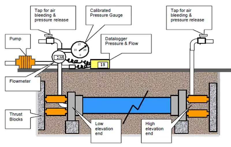
3. Preparation and Equipment
3.1 Test Pump and Gauge Selection
A calibrated, hand- or motor-driven test pump capable of reaching at least 1.5 × operating pressure is essential.
Pressure gauges must be accurate within ±1% of full-scale and calibrated against a national or accredited standard within the last 12 months.
3.2 Valves, Hoses, and Fittings
All valves and hoses used must be pressure-rated equal to or above test pressure, with quick-disconnect fittings to facilitate fast setup and teardown.
Bleed-off valves should allow staged pressure increases—first to 50% test pressure, then to 100%—to purge trapped air gradually.
3.3 Safety and Site Setup
-
Barricades and Signage: Restrict access to test area and display high-pressure warnings.
-
Personal Protective Equipment: Operators require safety glasses, face shields, and pressure-rated gloves.
-
Environmental Precautions: Ensure drainage of test water complies with local environmental regulations.
4. Testing Procedures
4.1 Filling and Venting
-
Slow Fill: Begin filling at the lowest point to minimize air entrainment.
-
Air Release: Open bleed-off valves at high points until a continuous water stream appears.
4.2 Pressure Application
-
Initial Pressure: Raise to 50% test pressure and hold for 5 minutes to detect gross leaks.
-
Full Test Pressure: Increase to full level (e.g., 1.5 × design or 500 psi, whichever is greater) and maintain for the specified hold time (typically 2 hours for mains).
4.3 Monitoring and Recording
Operators must log pressure readings at 15-minute intervals, noting any drops and corresponding water additions to maintain pressure.
Make-up water volumes are measured by metered flow or by known-volume vessels to quantify leakage rates.
5. Result Evaluation and Interpretation
5.1 Acceptance Criteria
-
Leakage Rate: Should not exceed 0.1 L/hr per 100 m of pipe for water mains.
-
Pressure Retention: Pressure drop must remain within gauge accuracy limits over the hold period.
5.2 Common Indications of Failure
-
Rapid Pressure Loss: Indicates gross leakage or burst.
-
Slow Decline: Suggests seepage at joints or small defects.
6. Troubleshooting and Best Practices
6.1 Air Entrapment
Ensure multiple venting points; repeat bleed-off if pressure curve shows early stalls.
6.2 Pump Performance
If the test pump fails to maintain pressure, verify seal integrity and fluid path for leaks.
6.3 Joint Inspection
Disassemble and re-grout or re-lubricate leaking joints—especially mechanical couplings.
7. Case Studies and Applications
7.1 Municipal Water Main Rehabilitation
A mid-sized city tested 2 km of 12″ Class 150 DI pipe, identifying three defective joints that would have caused unplanned shutdowns; corrective action saved an estimated $100 K in emergency repairs.
7.2 New Industrial Plant Loop
An industrial loop installed 1.5 × design pressure testing (525 psi) per client spec, resulting in zero failures and long-term reliability.
Comparison Table: Pressure Classes and Test Pressures
| Pressure Class | Nominal Pressure (psi) | Minimum Factory Hydrotest (psi) | Typical Field Test (psi) |
|---|---|---|---|
| Class 150 | 150 | 500 | 225 (1.5×150) |
| Class 250 | 250 | 500 | 375 (1.5×250) |
| Class 350 | 350 | 500 | 525 (1.5×350) |
| Class 500 | 500 | 500 | 750 (1.5×500) |
Six Common Questions & Detailed Answers
Q1: Why is the hydrostatic test pressure set at a minimum of 500 psi for ductile iron pipe?
A minimum 500 psi threshold ensures that all casting defects—including micro-porosity and inclusions—are exposed under pressure conditions significantly above typical operating levels. This buffer accounts for manufacturing variabilities and service stresses (e.g., transient surges) that could stress the pipe beyond nominal design. Moreover, AWWA C151/A21.51 explicitly requires this level at the point of manufacture to standardize quality across all producers and to safeguard against latent defects that might not be apparent at lower pressures. Testing at 500 psi also verifies the integrity of cement-mortar linings; if applied prior to testing, the lining could trap air pockets that compromise pipe performance—hence, the test is conducted before lining application to eliminate this risk. Finally, municipal specifications often demand an even higher safety factor—up to 75% of the pipe’s yield strength for 30″ and larger diameters—to ensure long-term durability under dynamic loading conditions.
Q2: How is leakage rate measured and what are acceptable limits for ductile iron mains?
Leakage measurement during a hydrostatic pressure test quantifies the make-up water needed to maintain test pressure over the hold period. Two primary methods are used:
-
Metered Flow Measurement: A precision flow meter in the supply line records total volume of water added to offset leaks .
-
Known-Volume Vessel: An accurately calibrated tank (e.g., 5 L) is emptied into the system each time pressure falls; the cumulative number of refills times tank volume equals total leakage .
Acceptable leakage rates for new ductile iron water mains are typically specified as no more than 0.1 L/hr per 100 m of pipe at field test pressure (usually 1.5×design pressure) . This criterion ensures that any seepage is negligible relative to normal operating flows and reflects both manufacturing quality and installation workmanship . For instance, a 1 km (1,000 m) main should leak no more than 1 L/hr under test conditions. Municipal contracts often tighten this to 0.05 L/hr per 100 m for critical transmission mains.
Careful calibration of flow meters and volume vessels is essential—errors of only ±0.01 L/hr can skew results significantly on short test runs. Temperature correction of water density and gauge accuracy (±1% full scale) must also be documented, per ANSI/AWWA C600 requirements, to validate acceptance.
Q3: Why must hydrostatic tests be performed before cement-mortar lining?
Cement-mortar linings improve corrosion resistance and hydraulic capacity, but if applied before hydrostatic testing, they can trap air pockets between lining and pipe wall. Under pressure, these pockets:
-
Expand and collapse cyclically, causing spalling or delamination of the lining, reducing its protective function.
-
Mask minor pinholes or microcracks in the pipe wall, preventing detection of defects that may propagate during service.
Therefore, ANSI/AWWA C151/A21.51 and sample specifications mandate that each pipe undergoes a factory hydrostatic pressure test of at least 500 psi prior to lining application. Once a pipe passes this test, it is suitable for lining; the lining process then embeds no residual stresses or entrapped air that could compromise pipe integrity.
In field installations, the same logic applies: newly assembled pipe runs are tested unlined to expose any joint leaks or casting flaws. Only after successful testing are joints dried and, if required, internal corrosion linings installed in situ or left as factory-lined. This sequence preserves lining adhesion and ensures that any defects are found and repaired before lining obscures them, enhancing long-term reliability and minimizing maintenance costs.
Q4: Can hydrostatic testing damage ductile iron pipe if done improperly?
When correctly executed, hydrostatic tests do not damage ductile iron pipe; in fact, they verify that each segment can safely withstand pressures well above service levels. However, improper procedures can introduce risks:
-
Rapid Pressure Increases: Exceeding recommended ramp-up rates (e.g., more than 50 psi per minute) can induce water hammer or transient stresses beyond pipe yield, leading to microfractures.
-
Air Entrapment: Failure to fully vent air leads to compressible air pockets that, under pressure, collapse suddenly and cause local shock loading on walls and joints.
-
Inadequate Support: Unsupported spans or unstable bedding during testing can deform pipe, especially at elevated pressures, resulting in permanent ovality or joint displacement.
Best practices to prevent damage include:
-
Controlled Ramp-Up: Increase to test pressure in stages (50% hold, then full pressure) with minimum 5 minute stabilization periods .
-
Multiple Vents: Install bleed valves at all high points, bleed until water flows free, and monitor pressure curves for anomalies indicating trapped air.
-
Proper Bedding and Anchoring: Ensure pipe is bedded per AWWA C600 specifications, with restrained joints at thrust points to avoid movement under test forces.
By following these guidelines and using calibrated equipment (±1% gauge accuracy), hydrostatic tests can reliably confirm pipeline integrity without inducing damage.
Q5: What environmental considerations apply to hydrostatic test water discharge?
Hydrostatic testing generates large volumes of clean water mixed with residual debris (rust, scale, joint lubricant). Discharge must comply with local environmental regulations to protect waterways and soils:
-
Sediment Control: Direct discharge through a sediment settling pond or silt fence prevents suspended solids from entering storm drains or natural creeks .
-
pH Adjustment: Cement-mortar dust can elevate water pH; neutralization with dilute acid (e.g., acetic acid) ensures pH 6–9 before release.
-
Contaminant Screening: If adhesives or corrosion inhibitors were used, water must be tested for total organic carbon (TOC) or other chemicals; permit-regulated disposal may be required .
Many jurisdictions classify test water as non-hazardous if it meets local discharge standards (turbidity < 50 NTU, pH 6–9). Operators should coordinate with municipal wastewater authorities or environmental agencies to secure permits or approval for offsite discharge.
Additionally, water reuse systems can capture and filter test water for subsequent testing jobs, reducing both environmental impact and fresh-water consumption. Portable filtration units with 5 µm filters and UV treatment allow multiple test cycles from a single water source, especially valuable in arid regions or during drought restrictions.
Q6: When should hydrostatic testing be repeated, and what are the costs of re-testing?
Hydrostatic tests must be repeated if a section fails to meet acceptance criteria—either excessive leakage or pressure loss beyond gauge tolerance. Factors triggering re-tests include:
-
Joint Leaks: Localized joint seepage requires re-torquing or replacement of gaskets, followed by re-isolation and retest of only the affected segment.
-
Valve or Fitting Failures: Any accessory that fails under test (e.g., gate valve stuffing box leak) must be repaired upstream of the defect; bypass piping may be used to isolate and re-test that portion.
-
Excessive Leakage Rates: If leakage exceeds 0.1 L/hr per 100 m, operators locate seepage points via acoustic detection before repairing and re-testing .
Re-testing costs vary by project scale:
-
Labor & Mobilization: Typical field crew rates (pump operator, technician) run $150–$200/hr; mobilization of equipment adds $500–$1,000 per site.
-
Materials: Gaskets and lubricants cost $5–$20 per joint, depending on size and type.
-
Water & Disposal: Fresh-water costs ($0.005–$0.02 per gallon) plus disposal fees or permit costs ($100–$500) can add up for large sections.
Overall, a single re-test of a 500 m main might cost $2,000–$4,000, so rigorous preparation and immediate joint corrections can minimize downtime and expense.
References:
- ANSI/AWWA Standards – American Water Works Association
- ASTM A536 – Standard Specification for Ductile Iron Castings
- ISO 2531:2009 – Ductile iron pipes, fittings, accessories and their joints for water applications
- Hydrostatic Testing – Wikipedia
- U.S. Environmental Protection Agency (EPA) – National Pollutant Discharge Elimination System (NPDES)
