Ductile iron pipe production involves a multi-stage casting process that transforms recycled ferrous scrap into high-performance, corrosion-resistant water‐ and wastewater piping systems. A clear, standardized flow chart—detailing raw-material preparation, spheroidization, centrifugal casting, heat treatment, lining, and finishing—ensures consistent quality and optimal mechanical properties.
1. Overview & Definitions
Ductile iron pipe is a cast‐iron product in which graphite appears as spheroids, offering superior ductility and toughness compared to gray cast iron. It is commonly used in water distribution, sewer, and industrial applications due to its high pressure rating, impact resistance, and long service life. A “flow chart” in this context refers to a process diagram that sequences each production step—from raw‐material batching through final packaging—to facilitate plant design, operator training, and quality assurance.
2. Material Composition & Metallurgy
2.1 Base Chemistry
Ductile iron typically contains 3.2–3.8 wt % carbon and 2.0–2.8 wt % silicon, similar to gray iron, but with a controlled nodularizer addition (magnesium or cerium) that modifies the graphite morphology. This spheroidal graphite microstructure produces a tensile strength of 400–600 MPa and elongation of 10–18 %—far exceeding gray iron’s 150–250 MPa tensile and <3 % elongation.
2.2 Spheroidization Treatment
After melting, a small ferro-magnesium or cerium alloy is injected into the ladle to achieve graphite nodules. Typical Mg-Fe alloys cost an extra USD 1,500–2,300/ton, but ensure nodule counts > 80 per mm² for optimal toughness .
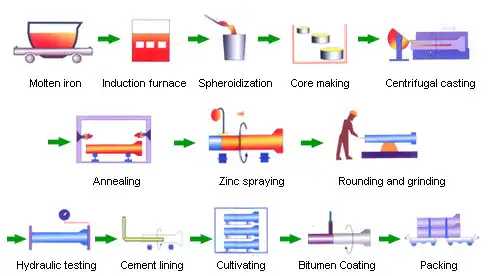
3. Manufacturing Process Flow Chart
Below is the standard six-stage flow chart used by leading manufacturers worldwide. It ensures repeatable quality, meeting ISO 2531, EN 545, AWWA C151, and related standards tataductura.
| Step | Description | Key Equipment | Primary Quality Checks |
|---|---|---|---|
| 1 | Raw Material & Charge Batching: Scrap iron, pig iron & alloys weighed and loaded into furnace. | Cupola/Induction Furnace | Chemical analysis (OES), temperature control |
| 2 | Melting & Inoculation: Melt bath heated to ~1,350 °C; inoculants added for graphite control. | Ladle, Mg/Ce Fe-alloy feeder | Magnesium content, nodule count |
| 3 | Centrifugal Casting: Molten metal spun in horizontal molds to form pipe bodies. | Centrifugal casting machine | Wall‐thickness gauge, visual mold inspection |
| 4 | Annealing / Austempering: Heat treatment improves ductility and residual stress relief. | Pit / rotary furnace | Hardness (Brinell), microstructure check |
| 5 | Lining & Coating: Internal cement-mortar lining and external epoxy/zinc coatings applied. | Lining machine, spray/coating booths | Lining thickness, holiday detection |
| 6 | Testing & Marking: Hydrostatic pressure, dimensional, and visual tests; stamping & packaging. | Hydrotester, calipers, stamping press | Pressure hold, dimensional tolerances, marking |
Table 1. Standard ductile iron pipe production flow chart.
4. Quality Control & Testing
4.1 Chemical Analysis
Each heat is sampled and analyzed by optical emission spectroscopy (OES) to confirm carbon, silicon, sulfur, phosphorus, and magnesium levels within ASTM A 536 or EN 1563 tolerances .
4.2 Graphite Morphology
Metallographic mounts from each cast length are etched and examined under optical microscopy to verify nodule count (≥ 80 n/mm²), nodule size, and graphite shape factor (≥ 0.8) .
4.3 Mechanical Tests
| Test | Standard | Acceptance Criteria |
|---|---|---|
| Tensile | ASTM A 536 / EN 1563 | ≥ 400 MPa for GJS-500-7 |
| Hardness (HB) | ASTM E 10 | 140–300 HB |
| Impact (Charpy V-Notch) | ASTM A 370 | ≥ 15 J at –20 °C |
| Elongation | ASTM A 536 | ≥ 10 % |
Table 2. Core mechanical tests and criteria.
4.4 Non-Destructive Testing
Pipes undergo 100 % hydrostatic testing at 1.5× design pressure (e.g., 525 psi for Class 350) and holiday detection on linings to locate coating defects > 0.5 mm.
5. Specifications & Applications
5.1 Standard Specifications
-
AWWA C151/C110/C111 for Class 50–350 pipe dimensions, joints (push-on, mechanical, restrained), and fittings.
-
ISO 2531 / EN 545 / EN 598 for metric nominal diameters DN 80–DN 1200, cement-mortar lining, zinc/polyethylene outer coatings.
5.2 Comparative Application Matrix
| Application | AWWA C151 (US) | ISO 2531/EN 545 (EU) | Key Differences |
|---|---|---|---|
| Drinking Water Mains | Class 150–350; DI-C-200/CL-350 | DN 80–DN 1200; K9/K12/K15 | Wall thickness profiles; pipe ends |
| Sewer & Wastewater | Special pressure ratings | EN 598 specifies lining | Slightly larger inside diameters |
| Industrial Fluids | Often unlined, epoxy-coated | Polyurethane lining option | Coating chemistries vary |
Table 3. Specifications vs. applications for ductile iron pipe.
6. Installation & Hydraulics
6.1 Jointing Methods
– Push-On Joints (AWWA C111 / EN 545): EPDM gasket, rubber ring, easy alignment; deflection up to 5° per joint.
– Mechanical Joints (AWWA C111): Bolted gland, thrust restraint without concrete thrust blocks.
– Restrained Joints (EN 545 / ISO 2531): Bolted locking segments, up to 16 bar rating without thrust blocks.
6.2 Hydraulic Performance
Ductile iron’s Hazen-Williams “C” factor typically ≥ 140 at installation and ≥ 120 after 20 years, outperforming PVC (C = 150→120) and cement-mortar-lined steel (C = 120→95), resulting in lower head losses and pump energy costs.
7. Lifecycle & Maintenance
7.1 Expected Service Life
Under normal soils, cement-mortar-lined ductile iron pipe lasts 60–100 years; in corrosive soils with polyethylene sleeving, 100+ years is common.
7.2 Corrosion Protection
– Internal Lining: Cement-mortar per AWWA C104 / EN 598 to inhibit pitting and graphitization.
– External Coating: Bonded zinc (≥ 200 g/m²) under bituminous or epoxy per EN 545; temporary asphaltic coating in the US per AWWA C110.
7.3 Maintenance Practices
Routine inspection includes leak detection surveys, cathodic protection potential monitoring, and flange/gasket replacements every 20–25 years to ensure uninterrupted performance.
FAQs
1. What Are the Six Key Steps in a Ductile Iron Pipe Production Flow Chart?
A clear production flow chart for ductile iron pipe comprises six essential stages: (1) Raw-material batching, where pig iron, scrap steel and alloying elements are weighed to recipe; (2) Melting & inoculation, where the charge is melted to ~1,350 °C and treated with magnesium-ferrosilicon or cerium alloys to achieve nodular graphite; (3) Centrifugal casting, in which the molten metal is spun in a horizontal mold to produce a dense, uniform pipe wall; (4) Annealing or austempering, a controlled heat-treatment step that relieves residual stresses and enhances ductility; (5) Lining & coating, typically involving a 2–3 mm cement-mortar lining inside and an epoxy or bonded zinc external layer for corrosion protection; and (6) Testing, marking & packaging, where each length undergoes hydrostatic pressure testing at 1.5× design pressure, holiday detection on linings, dimensional checks, and is finally stamped with size, class, batch ID, and shipped. Each stage is governed by strict standards—ASTM A 536, ISO 2531, AWWA C151, EN 545—to ensure consistency in mechanical properties, chemical composition, and dimensional accuracy. The segmentation into six steps aids plant engineers in process control, minimizes defects, and supports continual improvement through SPC (Statistical Process Control).
2. How Does Centrifugal Casting Improve Pipe Quality Compared to Static Molding?
Centrifugal casting, employed in ductile iron pipe production, uses high-speed rotation of a metal mold to force molten iron against the mold walls by centrifugal force. This results in a pipe with a compact, directional grain structure and virtually zero porosity on the inner and outer surfaces, as lighter impurities and slag are driven toward the bore, which is later machined away. Compared to static green-sand molds—where gas entrapment and mold-metal reactions can create surface defects—centrifugal casting yields pipes with superior wall-thickness uniformity (± 2 %) and higher tensile and fatigue properties. Additionally, the directional solidification reduces shrinkage defects and allows tighter dimensional tolerances, crucial for gasketed joints. Centrifugal casting also enhances graphite nodule distribution; nodules near the bore exhibit optimal spheroidization due to uniform cooling rates, translating into higher impact toughness and longer service life. This method is standard for all ISO 2531 and AWWA C151 ductile iron pipes.
3. Why Is Heat Treatment Critical for Ductile Iron Pipe?
After casting, ductile iron pipes often undergo annealing or austempering to refine microstructure and relieve stresses induced by rapid cooling. Annealing typically involves heating to 540–650 °C, holding for 1–4 hours, then slow cooling to transform any martensite or pearlite into ferrite and graphite nodules, thus enhancing ductility. Austempering—holding at 350–400 °C—produces ausferrite (a ferrite-carbon compound) matrix, offering a unique combination of high strength (up to 700 MPa) and good elongation (> 10 %). Without heat treatment, as-cast ductile iron can exhibit internal stresses leading to stress-corrosion cracking in service and lower fatigue life. Heat-treated ductile iron pipes consistently meet ASTM A 536 and EN 1563 mechanical requirements, including tensile strength, hardness, and impact energy, making this step indispensable for critical water-main and high-pressure applications.
4. What Are the Main Quality Checks at Each Flow-Chart Stage?
At the batching stage, OES confirms alloy chemistries within ± 0.02 wt % of targets. During inoculation, Mg content is measured by combustion analysis to ensure nodularity. In centrifugal casting, automatic wall-thickness gauges and infrared mold-temperature sensors guarantee uniform cooling. After heat treatment, Brinell hardness testers and metallographic samples verify matrix structure and hardness range (140–300 HB). Following lining, film-thickness gauges and holiday detectors (spark testers) locate voids larger than 0.5 mm. Finally, hydrostatic and dimensional tests ensure each pipe holds 1.5× working pressure without leakage and meets AWWA/ISO diameter and ovality tolerances. Stamping provides traceability for every batch.
5. How Do Global Standards Differ in Process Requirements?
While AWWA C151 (US) mandates centrifugal casting, cement-mortar lining per C104, and external asphaltic coating per C110, ISO 2531/EN 545 adds requirements for zinc–polyurethane external layers and allows restrained joints without thrust blocks up to 16 bar. AWWA permits factory epoxy linings for industrial pipelines, whereas EN 545 requires testing for poly-ethylene wrap systems (CEN/TR 16470). European standards specify tighter ovality (± 1 % vs. AWWA ± 3 %) and include acoustic leak detection protocols. AS/NZS 2280 (Australia/New Zealand) follows ISO but allows thicker cement linings for seawater systems. These differences reflect regional water chemistry, earthquake considerations, and jointing practices.
6. What Best Practices Improve Process Yield and Reduce Scrap?
Key best practices include precise charge control (using scrapped gating to minimize tramp elements), real-time monitoring of melt temperature and Si/C ratio, automated inoculant feeders to avoid over- or under-treatment, and optimized centrifuge speeds based on pipe diameter. Implementing Statistical Process Control (SPC) on hardness and nodule counts identifies drifts early. Regular maintenance of refractory linings prevents cold spots that cause misruns. Inline holiday detection after coating catches defects before packaging. Training operators on jointing and handling reduces damage during transport. These measures can reduce scrap rates from 8 % to < 2 %, significantly lowering production costs and environmental impact.
References:
- ASTM A536 – Standard Specification for Ductile Iron Castings
- ISO 2531:2014 – Ductile iron pipes, fittings, accessories and their joints for water applications
- AWWA Standards for Ductile Iron Pipe (C151, C110, C111)
- Ductile Iron – Wikipedia Overview and Metallurgy
- EN 545 & EN 598 Standards for Ductile Iron Pipes, Fittings and Joints
