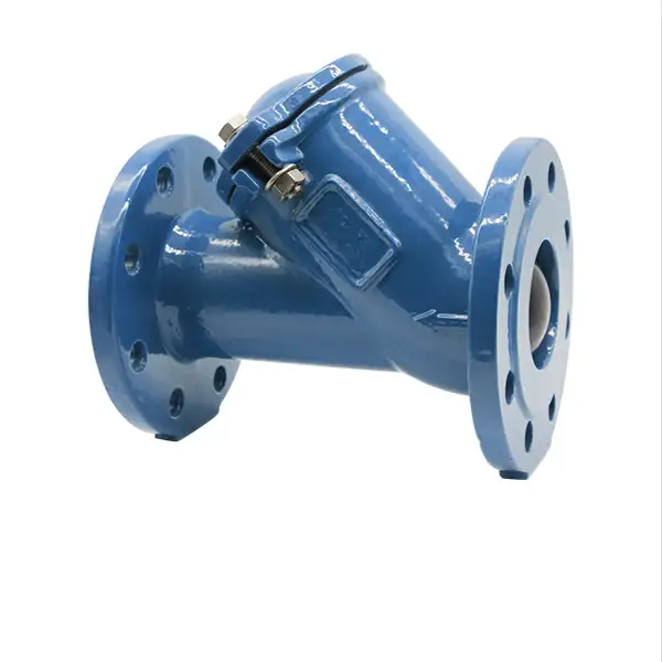
Ductile iron flanged ball check valves are widely used in waterworks, HVAC, and industrial piping to prevent backflow while offering corrosion resistance, high pressure ratings, and low maintenance. Manufactured to standards such as AWWA C508, API 6D, and EN 593, these valves feature a heavy-duty ductile iron body, a spring-loaded or gravity-operated ball closure, flanged end connections per ANSI/AWWA C110, and optional features like stainless-steel trim and epoxied-lined bores. Key benefits include bi-directional sealing, low pressure drop, and uncomplicated field service.
I. Standards & Specifications
Ductile iron flanged ball check valves must meet multiple national and international standards to ensure reliability and interchangeability:
-
AWWA C508 – “Resilient-Seated, Aluminum-Seated, and Ball Check Valves for Waterworks Service” specifies ductile iron construction, resilient elastomer seats, and test pressures to 400 psi .
-
API 6D – “Pipeline Valves” covers ball check designs for upstream oil and gas, mandating performance tests up to 2 000 psi .
-
EN 593 – European standard for check valves including ball check, with flanged ends per EN 1092-2 and temperature classes up to 200 °C .
-
ISO 5752 / EN 558 – Defines face-to-face dimensions and end-to-end lengths for flanged valves (short and long patterns) .
-
MSS SP-61 – Covers pressure testing for metal valves, including allowable leakage rates for seat and shell tests .
Together, these standards ensure that a 6″ AWWA C508 ball check from Manufacturer A can replace one from Manufacturer B without piping modifications.
II. Materials & Construction
1. Body & Bonnet
-
Ductile Iron (ASTM A536): Grade 65-45-12 or 70-50-05 for high tensile strength (65–70 ksi) and ductility .
-
Coatings: Fusion-bonded epoxy (≥ 250 µm) internally for corrosion protection; external coatings per AWWA C550 .
2. Ball & Seat
-
Ball: 316 SS or 17-4PH stainless steel for chemical resistance, polished to Ra ≤ 0.4 µm to ensure tight shut-off .
-
Seat: EPDM or PTFE elastomer bonded to ductile iron or stainless steel ring, providing bi-directional sealing up to 150 °C (PTFE) or 70 °C (EPDM) .
3. Trim & Fasteners
-
Springs (if spring-loaded): Hastelloy C or 316 SS to resist corrosion and maintain closure force .
-
Bolting: ASTM A193 B7 studs with ASTM A194 2H nuts, zinc plated or 316 SS for flanged joints .
4. End Connections
-
Flanges: ANSI/AWWA C110/A21.10 Class 150, drilled per ASME B16.1; optional Class 125 flanges .
-
Gaskets: Full-face or raised-face camprofile gaskets per AWWA Gasket Standard, typically EPDM with SBR binder .
III. Design Variations
Ball check valves employ a spherical closure member (the “ball”) that moves axially to permit flow and reseat under reverse flow conditions. Variations include:
-
Gravity-Operated (Sinking Ball): Heaviest ball seats by gravity, suited for horizontal installation; simple and low-cost.
-
Spring-Loaded (Floating Ball): Spring assists rapid closure and allows vertical installation; ideal for viscous fluids or low-flow conditions.
-
Weighted Ball with Adjustable Travel: Combines spring and weight, tuning reseat force and travel distance for specific service.
-
Unidirectional vs. Bidirectional Seal: Most designs seal in one flow direction; special resilient-seat designs offer bi-directional tightness.
Table 1. Ball Check Valve Variants and Characteristics
| Feature | Sinking Ball (Gravity) | Floating Ball (Spring) | Weighted/Adjustable Ball |
|---|---|---|---|
| Orientation | Horizontal only | Horizontal & Vertical | Horizontal & Vertical |
| Closure Speed | Moderate | Fast | Tunable |
| Backflow Prevention | Good | Excellent | Excellent |
| Minimum Flow for Closure | Higher (ball drop) | Lower (spring assist) | Adjustable |
| Typical Applications | Water mains | Oil, slurry, viscous | Specialty services |
Table 1. Comparison of common ductile iron flanged ball check valve designs.
IV. Performance Characteristics
1. Pressure & Temperature Ratings
Ductile iron flanged ball check valves per AWWA C508 are rated to:
-
Working Pressure: 150–300 psi (10–20 bar) depending on model and ball/seat material.
-
Hydrostatic Test: Shell test at 1.5× WP, seat test at 1.25× WP per MSS SP-61.
-
Temperature Range:
-
EPDM seats: −10 °C to +120 °C.
-
PTFE seats: −40 °C to +200 °C.
-
2. Flow Coefficient (Cv)
Ball check valves offer high Cv due to minimal obstruction:
-
Kv ≈ 0.9 × pipe diameter (mm) when fully open, outperforming swing-type checks in tight piping.
3. Pressure Drop
Typical ∆P at 2 m/s flow is < 0.1 bar for fully open valves, making them suitable for energy-sensitive applications.
V. Installation Best Practices
Proper installation maximizes valve life and reliability:
-
Piping Alignment & Support
-
Ensure valve is supported independently; piping strain can distort body and impede seating.
-
-
Orientation
-
Gravity (sinking ball): Body horizontal, arrow pointing downstream; ball must seat under gravity.
-
Spring (floating ball): May be installed vertical (flow up) or horizontal; check manufacturer guidance.
-
-
Straight-Run Requirements
-
Maintain ≥ 5 × DN upstream and 2 × DN downstream for undisturbed flow, per DFT guidelines.
-
-
Flange Gasket & Bolting
-
Use compatible gasket (EPDM camprofile for AWWA flanges) and torque bolts uniformly in star pattern to 70-90 ft·lb for 2″–8″ sizes; larger sizes per OEM tables.
-
-
Commissioning
-
Flush line before operation; cycle valve under no-flow conditions to verify movement and seal.
-
VI. Maintenance & Troubleshooting
Routine Inspection
-
Visual Checks: Inspect for external corrosion, leaks around flanges and cover bolts.
-
Operational Testing: Quarterly flow reversal tests ensure ball closure; watch for chatter indicating turbulence or debris.
Common Issues & Remedies
| Symptom | Possible Cause | Corrective Action |
|---|---|---|
| Leakage Past Seat | Worn or damaged seat/ball | Replace seat insert; polish or replace ball |
| Sticking Ball | Debris accumulation; corrosion | Flush line; disassemble and clean internals |
| Excessive Noise | High‐velocity flow; poor support | Add upstream straight run; check support/brackets |
| Flange Leakage | Under-torqued bolts; damaged gasket | Retorque bolts; replace gasket |
Table 2. Troubleshooting common ball check valve issues.
VII. Comparative Analysis
Below is a side-by-side comparison of flanged ball check, swing check, and lift check valves in ductile iron bodies:
| Feature | Ball Check | Swing Check | Lift Check |
|---|---|---|---|
| Seal Tightness | Bi-directional, tight | Uni-directional, resilient | Uni-directional, metal or resilient |
| Orientation Options | Gravity: horizontal; Spring: any | Horizontal only | Vertical only |
| Flow Path | Straight through | Slightly angled hinge | Narrow globe path |
| Response Speed | Fast (spring assist) | Moderate | Fast |
| Pressure Drop | Low (< 0.1 bar) | Low–moderate | Moderate |
| Maintenance Ease | High—single ball/seat | Moderate—hinge & disc | Moderate—stem & disc |
Table 3. Comparison of common ductile iron check valve types.
VIII. Application Examples
-
Municipal Water Mains:
-
Spring-loaded ball checks prevent backflow during pump shutdowns with minimal pressure loss, essential in booster stations.
-
-
Fire Protection Systems:
-
UL/FM-listed ball checks with EPDM seats provide rapid closure to avoid water hammer and ensure compliance with NFPA 13 regulations.
-
-
HVAC Condensate Lines:
-
Gravity ball checks offer drip-leg protection, preventing steam ingress into boiler feed pumps.
-
-
Industrial Process:
-
Corrosive fluids in chemical plants use PTFE-sealed ball checks to handle aggressive media at elevated temperatures.
-
IX. Selection & Sizing Criteria
1. Flow Rate & Cv Matching
-
Calculate required Cv using manufacturer curves, then select valve size with Cv ≥ required for ∆P ≤ 0.1 bar.
2. Material & Seat Compatibility
-
Match EPDM for water, PTFE for chemicals, and assure metal‐to‐metal core for abrasive slurries.
3. Orientation & Space Constraints
-
For limited headroom, spring designs allow vertical mounting; gravity types best where horizontal runs are straight and accessible.
4. Pressure & Temperature Ratings
-
Ensure working pressure rating ≥ 1.25× system pressure and seat material temperature range covers operating extremes.
5. Actuation & Automation
-
Though ball checks are automatic, consider adding remote position indicators or limit switches for SCADA integration in critical services.
YouTube Video Tutorial
<iframe width=”500″ height=”500″ src=”https://www.youtube.com/embed/_hacKvsgRa4″ frameborder=”0″ allowfullscreen></iframe>
*How to install and maintain ductile iron ball check valves
Six Common Questions
1. What’s the difference between spring-loaded and gravity ball check valves?
Spring-loaded (floating) ball checks incorporate a corrosion-resistant spring that pushes the ball against the seat as soon as flow reverses, allowing reliable closure even in vertical installations or low-flow conditions. Gravity (sinking) ball checks rely solely on the ball’s weight to seal; they must be installed horizontally and require sufficient reverse pressure to overcome ball inertia. Spring designs close faster, reducing water hammer, while gravity types are simpler and lower-cost but limited to horizontal runs.
2. Can ball check valves handle slurries or solids-laden fluids?
Yes—ball check valves with metal-to-metal seats or PTFE-coated seats tolerate slurries better than resilient seats, as they resist abrasion. However, solids may lodge behind the ball, preventing full closure. For heavy solids service, a swing check with a flapper and guide may perform better, or a ball check with a guided cage to prevent ball misalignment. Always specify hardened trim and regular flushing for slurry applications.
3. How often should ball check valves be inspected in municipal systems?
Annual inspection is recommended: cycle the valve manually (if possible), visually inspect for corrosion, and check for seat leakage under 1.25× working pressure. In critical services (e.g., fire protection) or aggressive environments, semi-annual checks are prudent. Replace EPDM seats every 10–15 years, or sooner if chemical exposure or UV degrades elastomers.
4. What causes ball check valve chatter, and how can it be stopped?
Chatter occurs when flow reverses rapidly or turbulence near the valve causes the ball to oscillate. Remedies include installing upstream straight pipes (≥ 5 × DN), adding flow-straightening vanes or orifice plates, switching to a spring-loaded design for quicker closure, or using a damped cushion to slow the ball’s movement. Proper support and alignment also prevent vibration-induced chatter.
5. Are flanged ball check valves interchangeable across manufacturers?
Yes, when built to the same standards (AWWA C508, EN 593, API 6D) and face-to-face dimensions (ISO 5752/EN 558). Flange drilling per ANSI B16.1 or EN 1092-2 ensures bolt-pattern compatibility. Minor differences in cover bolt patterns or height above pipe may require bracket adjustments, so always verify dimensional drawings before retrofits.
6. How do you size a ball check valve for minimal pressure drop?
Calculate system flow rate (Q) and desired ∆P (e.g., ≤ 0.1 bar). From manufacturer’s Cv tables, choose the smallest valve size whose Cv (flow coefficient) satisfies Q/√∆P ≤ Cv. Oversizing marginally reduces ∆P further but may slow closure; under-sizing raises ∆P and risks chatter. Consulting a valve datasheet with measured Cv curves is essential for accurate sizing.
