This comprehensive guide covers ductile iron flanged AWWA C515 gate valves in depth, fulfilling needs from material standards to installation best practices. In nine detailed sections, you’ll learn about the AWWA C515 standard scope and history, design features, materials and coatings, valve types and end connections, dimensional charts for 3″–54″ valves, pressure ratings, manufacturing processes, installation and maintenance, and application selection.
1. AWWA C515 Standard Overview
The AWWA C515 standard—“Reduced-Wall, Resilient-Seated Gate Valves for Water Supply Service”—was first published in 2009 and revised in 2015 and 2020. It specifies design, materials, test methods, and performance for ductile iron gate valves sized 3″ (75 mm) through 54″ (1350 mm) NPS, covering both non-rising stem (NRS) and outside screw-and-yoke (OS&Y) valves. Valves must operate in temperatures from 33 °F to 125 °F (0.6 °C–52 °C) and withstand recommended minimum working water pressure of 200 psi (1 380 kPa). The standard mandates hydrostatic testing at 1.5 × design pressure and requires resilient-seated wedges encapsulated in EPDM rubber for leak-proof sealing.
2. Design Features & Materials
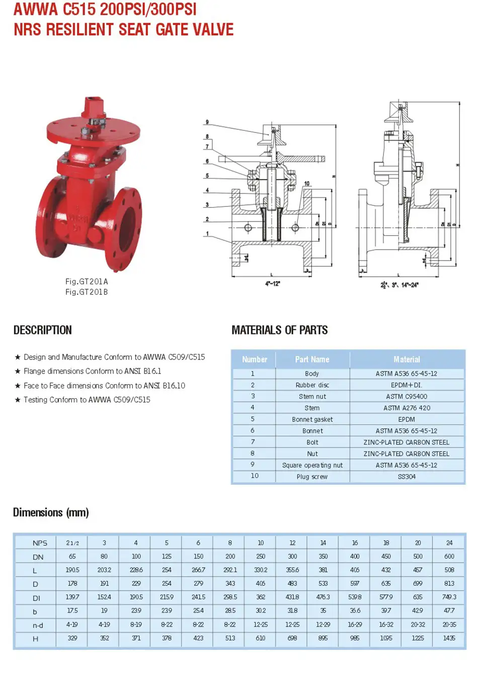
2.1 Body, Bonnet & Wedge
-
Ductile Iron Casting: ASTM A536 Grade 65-45-12 ensures tensile strength ≥ 483 MPa and elongation ≥ 12 %.
-
Bonnet: Bolted to the body with stainless-steel bolts; pressure seal joints optional for sizes > 16″.
-
Wedge: Resilient Sluice design, rubber-encapsulated EPDM core, conforming to AWWA C550 fusion-bonded epoxy.
2.2 Stem & Packing
-
Stem Material: Stainless steel (304 or 316) for corrosion resistance, non-rising in NRS valves, rising in OS&Y types.
-
Packing: Graphite or PTFE rings compressed by gland flange; live-load springs optional for dynamic sealing.
3. Valve Types & End Connections
Ductile iron gate valves per AWWA C515 are offered with:
| Series | Connection | Stem Type | Rated Pressure | Size Range |
|---|---|---|---|---|
| 10FW | Flanged | NRS Hand-wheel | 250 psi | 2″–16″ |
| 10FN | Flanged | NRS Op-nut | 250 psi | 2″–16″ |
| 9600FJ | Flanged × MJ | NRS Op-nut | 300 psi | 3″–12″ |
| 801 | Flanged | OS&Y Hand-wheel | 300 psi | 3″–12″ |
Table 1: Common AWWA C515 Gate Valve Series & Connections.
-
Flanged Ends: ANSI B16.1 Class 125 bolt patterns, raised face, gasket sealing.
-
Mechanical Joint (MJ): Ductile iron gland, gasket, bolts per AWWA C111.
-
Threaded Ends: IPS taper thread for sizes ≤ 2″; rare in large diameters.
4. Dimensions & Size Chart
Below is a sample of AWWA C515 NRS flanged valve dimensions for Class 250 (250 psi) hand-wheel valves:
| Nominal Size | Face-to-Face (L) | Flange OD (A) | Bolt Circle (C) | # Bolts (n) | Bolt Dia. (d) |
|---|---|---|---|---|---|
| 3″ (75 mm) | 7″ (178 mm) | 104.8 mm | 165.1 mm | 4 | 19 mm |
| 6″ (150 mm) | 12″ (305 mm) | 177.8 mm | 241.3 mm | 8 | 19 mm |
| 10″ (250 mm) | 18″ (457 mm) | 279.4 mm | 362.0 mm | 8 | 22 mm |
| 16″ (400 mm) | 24″ (610 mm) | 406.4 mm | 533.4 mm | 12 | 22 mm |
| 24″ (600 mm) | 36″ (914 mm) | 609.6 mm | 762.0 mm | 12 | 22 mm |
Table 2: Face-to-Face and Flange Dimensions for Class 250 Valves
5. Pressure Ratings & Performance
-
Class 250: 250 psi (1.72 MPa) working pressure @ 38 °C for NRS valves.
-
Class 300: 300 psi (2.07 MPa) working pressure for MJ and OS&Y valves (Series 9600FJ, 801).
-
Hydrostatic Test: Shell tested at 1.5× working pressure; seat tested in both directions at 1.1× working pressure.
6. Manufacturing & Coating Processes
-
Casting: Sand-cast ductile iron using magnesium nodulization, heat-treated per ASTM A536.
-
Machining: CNC machining for faces, bodies, and wedge seats to ± 0.5 mm tolerance.
-
Internal Coating: Fusion-bonded epoxy per AWWA C550, 12 mil thickness for corrosion resistance.
-
External Coating: Shop-applied asphaltic or epoxy primer + finish coat to AWWA C550 standards.
7. Installation & Maintenance
-
Gasket: EPDM full-face gaskets per ASME B16.21; inspect before assembly.
-
Torque Sequence: Star pattern, three-pass tightening to manufacturer-specified torque (e.g., 175 Nm for 22 mm bolts).
-
Periodic Re-torque: After 24 h and at 6-month intervals to compensate gasket relaxation.
-
Inspection: Annual external coating checks; hydrostatic retesting every 5 years for critical services.
8. Application Guide & Selection Tips
-
Municipal Water: Series 10FW hand-wheel valves for ease of operation in buried systems.
-
Fire Protection: Series 801 OS&Y valves with OS&Y rising stem for visual position indication; UL/FM approved.
-
Industrial: Series 9600FJ flanged × MJ valves for combined flange and mechanical joint requirements; 300 psi rating.
-
Retrofit: Compact C515 “reduced wall” design allows lighter weight and easier handling compared to older C500-based C509 valves.
9. Quality Assurance & Traceability
Every valve is stamped with heat number and serial number, accompanied by a mill certificate. Standard tests include:
-
Tensile & Impact: Per ASTM A536.
-
Hydrostatic Testing: Shell and seat.
-
Dimensional Inspection: Calibrated gauges for face-to-face and flange dimensions.
-
Non-Destructive Testing: Magnetic particle or ultrasonic for critical welds (pressure seal bonnets).
-
Third-Party Approvals: UL/FM listings, NSF-61/NSF-372 certification for potable water.
Common Questions & Answers
Q1: How does the “reduced-wall” design in AWWA C515 differ from older C509 valves?
AWWA C509, introduced in 1980, was based on cast iron physical properties, requiring thicker walls to withstand working pressures. C515 leverages ductile iron’s superior strength (tensile ≥ 483 MPa, elongation ≥ 12 %) to reduce wall thickness, lowering weight by up to 20 % while maintaining or exceeding the same pressure rating of 200–250 psi. Reduced‐wall valves are easier to handle on-site, decrease shipping costs, and improve erection safety. Dimensions between C509 and C515 may differ in face-to-face length (C515 often shorter by 1–2 inches), so direct interchange requires checking OEM dimension tables.
Q2: What are the operational differences between Non-Rising-Stem (NRS) and Outside-Screw-and-Yoke (OS&Y) AWWA C515 gate valves?
Non-rising-stem (NRS) gate valves feature an internal stem that turns within the valve bonnet without visible travel of the stem, making them more compact and suitable for buried or confined installations where vertical space is limited. In contrast, outside-screw-and-yoke (OS&Y) valves display the stem’s axial movement above the bonnet, providing an immediate visual indication of the valve’s open or closed position. NRS valves typically have fewer exposed parts, reducing the risk of external corrosion on the stem threads, whereas OS&Y valves require regular maintenance of the exposed threads and yoke to prevent galling and rust. Because the stem in an NRS valve rotates inside the valve body, these valves generally experience lower operating torque but can suffer from internal packing wear if debris enters the bonnet cavity. OS&Y designs, by virtue of the rising stem, keep the wedge and seating surfaces isolated from the stem threads, allowing for easier packing replacement under pressure without disassembly of the valve body. When specifying for waterworks, engineers often choose NRS valves (Series 10FN/10FW) for buried mains and OS&Y valves (Series 801) for locations where position indication for safety-critical services—such as fire protection—is paramount. Finally, installation practice varies: NRS valves may be installed without special backing supports because they exert no vertical thrust, whereas OS&Y valves need support to counteract the axial load transmitted through the yoke when operated manually.
Q3: What testing and certification procedures do AWWA C515 gate valves undergo to ensure quality and compliance?
Prior to shipment, every AWWA C515 valve must pass a hydrostatic shell test at 1.5× its working pressure to verify body integrity and a seat test at 1.1× working pressure in both directions to ensure leak-tight closure. In addition, valves sized 3″–24″ require factory inspection certificates confirming conformance to all dimensional tolerances specified in AWWA C515 and AWWA C550 for fusion-bonded epoxy linings. Certified valves bear permanent markings—including manufacturer name, year of manufacture, pressure rating, and heat number—cast into the body for traceability and future maintenance reference. Third-party listings such as UL (Underwriters Laboratories) and FM (Factory Mutual) evaluate additional performance criteria—such as fire-service temperature cycling—before granting approvals commonly required in fire protection specifications. NSF/ANSI 61 and NSF/ANSI 372 certifications ensure the valve’s internal epoxy lining and materials meet safe drinking water requirements, with test reports available upon request. Non-destructive testing (magnetic particle or ultrasonic) is applied to bonnet welds or pressure-seal surfaces on valves larger than 16″ to detect subsurface defects. Dimensional inspection uses calibrated gauges to confirm critical dimensions such as face-to-face length, flange bolt-circle diameter, and bolt-hole position tolerances are within ±1.5 mm of standard values. Finally, factory-performed torque verification ensures the stem and bonnet bolts meet required bolt-preload values, guaranteeing reliable stem thrust bearing performance and packing compression under service conditions.
Q4: What are best practices for field repair and troubleshooting of AWWA C515 gate valves?
When valves fail to seal or operate smoothly, first isolate the valve by closing adjacent upstream and downstream valves and relieving the internal pressure per AWWA C515 safety guidelines before attempting any repair. Begin troubleshooting by cycling the valve from full open to full closed to dislodge any trapped debris in the wedge or seat area; in some cases, minor obstruction can be cleared by multiple operations under pressure. If leakage persists past the stem packing, tighten the gland flange bolts in a star pattern, applying torque in three stages—30%, 60%, then 100% of specified values—to re-compress the packing without over-stressing the stems. For packing replacement, NRS valves allow packing renewal by removing the stuffing box cap and extracting old rings through the bonnet cavity, whereas OS&Y valves permit live-under-pressure packing changes using split packing assemblies and special packing extraction tools. Severe leaks at the seat may require valve removal for disassembly on a workbench; follow the manufacturer’s torque sequence for bonnet bolt removal to avoid warping the body joint. Inspect the epoxy–rubber encapsulated wedge for cuts, tears, or delamination; replace the wedge assembly if damage is evident, ensuring the new wedge meets AWWA C550 lining thickness and hardness specifications. Before reinstallation, verify flange face and pipe end condition; clean and dress any nicks or corrosion to prevent future leaks. Finally, conduct a partial on-site hydrostatic test by pressurizing the valve to working pressure and checking for external leaks around packing, flanges, and body joints, followed by a functional seat test if permissible under system constraints.
Q5: How should tapping gate valves be specified and used under AWWA C515?
Tapping gate valves—valves with integral tapping flange and mechanical cutter—enable service connections to live mains without system disruption, and AWWA C515 covers both the valve and tapping accessories for sizes 3″–24″. When specifying tapping valves, include the maximum tapping pressure (commonly 200 psi) and tapping range (e.g., 4″–12″ branch size), ensuring compatibility with the main’s pressure rating and nominal diameter. Engineers must also select the correct tapping sleeve—match the sleeve type (split-tee vs. full-body) and gasket material (EPDM for potable water) to the main pipe material and surface finish to achieve a uniform seal. AWWA C515 tapping valves require a full-size tapping cutter recommended by the valve manufacturer; verify that the valve’s waterway is free of depressions and adequately sized to accept the cutter diameter without binding. Installation involves drilling pilot holes through the tapping flange under low pressure, followed by controlled cutting to minimize vibration and prevent valve misalignment. After tapping, close the valve and remove the cutter per manufacturer instructions, leaving a clean, full-diameter branch port. Finally, pressure-test the new branch line at or above design pressure before connecting service piping, documenting test results and recording the tapping machine and cutter serial numbers for traceability.
Q6: How do lifecycle costs of AWWA C515 ductile iron gate valves compare to other valve types in waterworks service?
When evaluating total cost of ownership, AWWA C515 resilient-seated ductile iron gate valves often deliver the lowest lifecycle cost for large-diameter water mains due to their durability, low leakage rates, and minimal maintenance requirements. Compared to bronze or carbon-steel gate valves, ductile iron valves carry a lower initial material cost per unit diameter—up to 30% less—while providing equivalent or superior pressure ratings and corrosion resistance when properly coated and lined. Operating torque for C515 valves is reduced by the low-friction thrust bearings in NRS designs or the externally lubricated rising stems in OS&Y types, translating to lower actuator or manual torque wrench costs over the valve’s 50-year design life. Maintenance expenditures are further minimized by the EPDM-encapsulated wedges that resist abrasion and chemical attack, reducing the frequency of seat and packing replacements relative to metal-seated or unsupported rubber-seat valves. When factoring in downtime costs for system shut-downs and the labor to re-torque or repack flanges, resilient-seated ductile iron gate valves typically show a 20–40% lower total lifecycle cost compared to similar-size butterfly or plug valves in potable water service. Even when including occasional replacement of EPDM gaskets and repacking every 10–15 years, the robust casting and standardized maintenance procedures keep overall lifecycle costs competitive, particularly for utilities with large valve inventories and stringent leak-rate targets.
References:
- AWWA C515 Standard – American Water Works Association
- ASTM A536 Standard Specification for Ductile Iron Castings – ASTM International
- AWWA C550 Standard for Protective Fusion-Bonded Epoxy Coating – American Water Works Association
- ASME B16.21 – Nonmetallic Flat Gaskets for Pipe Flanges – ASME International
- Gate Valve – Wikipedia (Technical overview and types)
