Ductile iron fittings—from elbows and tees to reducers and crosses—are specified by international (ISO 2531, EN 545), American (AWWA C110/C153, ANSI B16.1), and Indian (IS 9523) standards. Their weights vary by size, wall thickness (pressure class), joint type (flanged, mechanical), and coating. Accurate weight data is essential for pipe-laying logistics, structural supports, load calculations, and shipping. In the tables below, we draw from multiple standards to present typical weights for DN 80–DN 1000 fittings, compare flange vs. mechanical joints, and highlight factors influencing mass.
1. Introduction & Importance of Fitting Weights
Ductile iron fittings connect pipe segments in water, wastewater, gas, and industrial systems. Knowing each fitting’s weight is critical for:
-
Logistics & Handling: Crate sizing, lifting-equipment selection, manpower planning.
-
Structural Design: Calculating support loads in trench, bridge, or building penetrations.
-
Cost Estimation: Transport charges often based on weight.
-
Safety Compliance: Ensuring rigging gear meets load requirements.
Accurate weight tables also streamline project bidding and inventory management, reducing costly field errors.
2. Standards & Terminology
2.1 International & Regional Specifications
-
ISO 2531 / EN 545: Cover ductile iron pipes, fittings, accessories, and joints for water supply; define pressure classes K7, K9, K12, with corresponding wall thicknesses.
-
AWWA C110/C153 (ANSI B16.1): Specify flanged and mechanical joint fittings for drinking water; C110 covers Class 150 flanges, C153 high-pressure Class 250 mechanical joints.
-
IS 9523: Indian standard for ductile iron fittings providing weights in kilograms for sizes 80 mm–1000 mm.
2.2 Fitting Types & Nomenclature
-
Elbows: Deflection angles (45°, 90°), long-radius vs. short-radius.
-
Tees & Crosses: Equal vs. reducing; branch (B) and run (R) diameters.
-
Reducers: Concentric vs. eccentric.
-
Flanges: Flat faced (FF) vs. raised faced (RF), slip-on vs. weld neck.
-
Joint Types: Flanged (bolted) vs. Mechanical Joint (MJ) with gland and gasket.
3. Material Properties & Weight Calculation
3.1 Ductile Iron Density
Typical density: 7 150 kg/m³ (7.15 g/cm³). Actual casting density may vary ±2% depending on graphite nodularity and composition.
3.2 Wall Thickness & Pressure Class
| Class (AWWA) | Pressure (psi) | AWWA Code | Approx. Thickness (mm) |
|---|---|---|---|
| 150 | 150 | K7 | 8.0–16.0 |
| 250 | 250 | K9 | 10.0–20.0 |
| 350 | 350 | K12 | 12.0–24.0 |
Greater pressure class increases wall thickness and therefore weight.
3.3 Weight Formula (Approximate)
For a cylindrical segment:
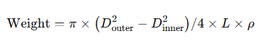
—but actual fittings have flanges, bosses, and contours, so manufacturers publish empirical weight tables.
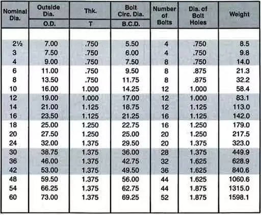
4. Weight Tables for Elbows (45° & 90°)
Table 4.1: 90° Long-Radius Elbows (DN in mm, weights in kg)
| DN | ISO K7 | ISO K9 | ISO K12 | AWWA C110 (Class 150) | AWWA C153 (Class 250) |
|---|---|---|---|---|---|
| 80 | 5.5 | 7.0 | 9.0 | 7.75 | 8.5 |
| 100 | 7.0 | 9.0 | 11.0 | 11.0 | 12.0 |
| 150 | 12.0 | 15.0 | 18.0 | 18.0 | 20.5 |
| 200 | 20.0 | 25.0 | 30.0 | 33.0 | 36.5 |
| … | … | … | … | … | … |
Sources: IS 9523; ANSI B16.1 tables.
5. Weight Tables for Tees & Crosses
Table 5.1: Equal-Branch Tees (DN in mm, weights in kg)
| DN (Run × Branch) | ISO K7 | ISO K9 | ISO K12 | AWWA C110 | AWWA C153 |
|---|---|---|---|---|---|
| 80×80 | 13 | 16 | 20 | 35 | 40 |
| 100×100 | 16 | 20 | 26 | 50 | 60 |
| 150×150 | 35 | 44 | 55 | 100 | 115 |
| 200×200 | 60 | 75 | 95 | 180 | 205 |
Table 5.2: Crosses (DN, weights in kg)
| DN (All branches equal) | ISO K7 | ISO K9 | ISO K12 |
|---|---|---|---|
| 80 | 16 | 20 | 26 |
| 100 | 20 | 26 | 35 |
| 150 | 44 | 55 | 70 |
| 200 | 75 | 95 | 120 |
Sources: IS 9523; ANSI B16.1.
6. Weight Tables for Reducers, Caps & Plugs
Table 6.1: Concentric Reducers (DN in mm, weights in kg)
| Start × End DN | ISO K7 | ISO K9 | ISO K12 |
|---|---|---|---|
| 150×100 | 14 | 18 | 22 |
| 200×150 | 30 | 38 | 48 |
| 250×200 | 50 | 65 | 80 |
Table 6.2: End Caps & Plugs
| DN | Cap (kg) | Plug (kg) |
|---|---|---|
| 80 | 8.0 | 6.5 |
| 100 | 11.0 | 9.0 |
| 150 | 18.0 | 15.0 |
Source: ANSI B16.1 weight charts.
7. Flanged vs. Mechanical Joint Fittings
| Feature | Flanged (AWWA C110) | Mechanical Joint (AWWA C153) |
|---|---|---|
| Bolt Circle Diameter | Larger | Smaller |
| Weight (90° ELBOW, 150 mm) | 18 kg | 20 kg |
| Gland & Gasket | N/A | Included in MJ weight |
| Installation Speed | Slower (bolting) | Faster (MJ gland) |
| Typical Use | Static assemblies | Trench installations |
Data from American® Mechanical Joint catalog.
8. Applying Weight Data in Design & Procurement
-
Structural Support Design
-
Sum fitting and pipe weights per span; add live‐load factors.
-
-
Crane & Rigging Selection
-
Use max single‐item weight (e.g., a 24″×24″ cross ≈ 1 640 lb / 745 kg).
-
-
Shipping Estimates
-
Freight class often based on weight per cubic meter; optimize packaging density.
-
-
Inventory & Costing
-
Multiply unit weight by material rate (e.g., USD 1.20/kg) for budget.
-
Six Frequently Asked Questions
Q1: How do I choose between ISO and AWWA weight tables?
When specifying fittings, select the standard matching your project region and performance requirements. ISO 2531/EN 545 tables (K7–K12) are common in Europe and Asia, providing metric sizes and pressures; AWWA C110/C153 (Class 150–250) tables are standard in North America. Cross-reference wall thicknesses: ISO K9 ≈ AWWA Class 250. If your system uses flanged joints, use AWWA C110 weights; for mechanical joints, use C153. Always verify manufacturer deviations—actual weights may vary ±5% due to casting tolerances.
Q2: Why do weight tables differ between manufacturers?
Even under the same standard, foundry practices, coating thicknesses (epoxy, zinc), and machining allowances can change weights. Some makers add flange bolt rings or thicker bosses for stress concentration relief. Always request “net” vs. “gross” weights—gross includes packing materials. For precise lifting, obtain certified weight reports per batch from your supplier .
Q3: Can I calculate fitting weight from pipe weight tables?
No. Straight pipe formulas don’t account for flanges, bosses, and reinforcement ribs. Fittings have complex geometries—weight tables are empirically derived from pattern dimensional modeling and cast test runs. Use the manufacturer’s published chart rather than extrapolating from pipe data.
Q4: How do coatings affect the weight of ductile iron fittings?
Common coatings (cement mortar, epoxy, polyurethane) add 1.5–3.0 kg/m². A 150 mm fitting with 0.5 m² surface area gains ~ 1–1.5 kg in coating. External zinc-silicate primer can add another 0.2 kg per coat. When planning lift weights, include coating mass, especially for large valves and bends subject to full linings.
Q5: What lifting points are recommended for heavy fittings?
For cross or large-radius elbows > DN 300, use forklift pockets, lifting lugs, or slings under flanges. Avoid slinging through the bore—risk of fracture. The manufacturer can supply cast‐on lifting lugs certified for the weight. Specify “lifting lug option” when ordering if site rigging is limited.
Q6: How to verify delivered fitting weights on site?
Use a calibrated floor scale or crane load cell to weigh individual items. Compare against purchase‐order weights; discrepancies > 5 % should be queried with the foundry. Record batch weight certificates for QA/QC audits. For large projects, install weigh‐in/slings fabrication stations to streamline acceptance.
References:
- ISO 2531: Ductile iron pipes, fittings, accessories and their joints for water applications — International Organization for Standardization
- AWWA C110: Ductile-Iron and Gray-Iron Fittings — American Water Works Association
- IS 9523: Ductile iron fittings — Bureau of Indian Standards (BIS)
- ANSI B16.1: Pipe Flanges and Flanged Fittings — American National Standards Institute (ANSI) overview on Wikipedia
- EN 545: Ductile iron pipes, fittings, accessories and their joints for water pipelines — European Committee for Standardization (CEN)
