Ductile iron filler flanges—also known as spacer or “filler” flanges—bridge gaps between mismatched pipe ends or equipment flanges, enabling a flat-gasket seal when O-rings or raised-face connections are impractical. Manufactured in sizes from 3″–16″ (standard) and thicknesses from 5/8″ up to 3″ (with multi-piece assemblies for greater gaps), these flanges are faced and drilled per ANSI/AWWA C110 templates (125 lb standard, 250 lb optional) to match existing bolt circles. Constructed of ASTM A536 ductile iron (or ASTM A48 grey iron variants) and often shop-coated with fusion-bonded epoxy, filler flanges deliver full working pressures (250 psi, up to 350 psi with special gaskets on sizes ≤ 24″) and ensure mechanical integrity in water, wastewater, and industrial piping systems. Proper installation—following AWWA C600 and DIPRA guidelines—requires careful alignment, torque control, and use of stainless-steel fasteners to maintain leak-tight performance and service lives exceeding 50 years.
1. Overview & Applications
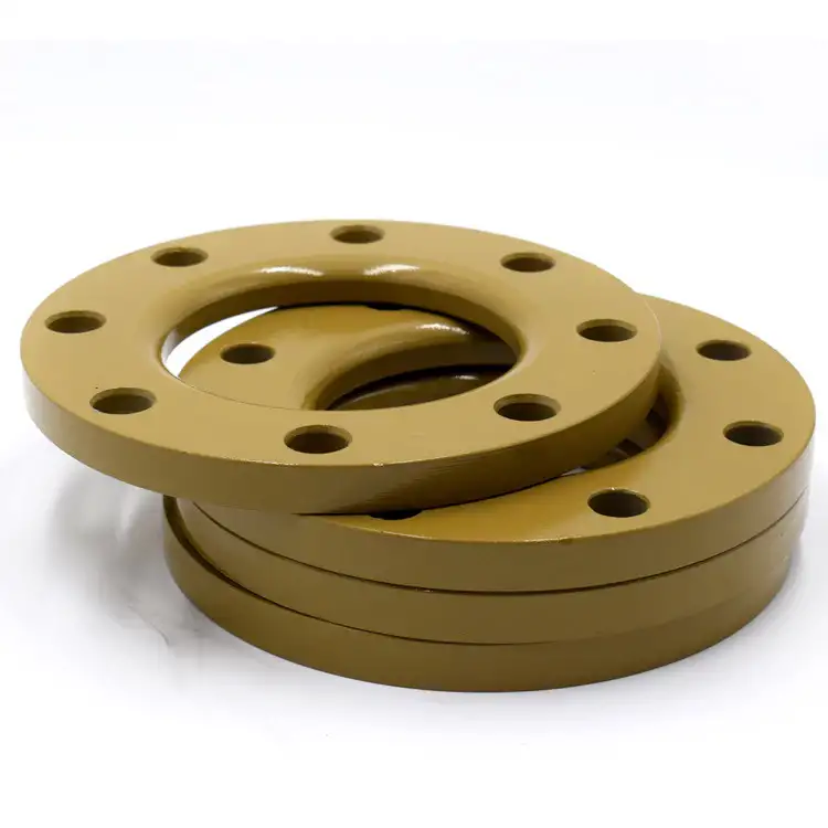
Ductile iron filler flanges are specialty flange adapters used to create a flat-face connection when mating with raised-face or O-ring flanges is not feasible, such as on legacy valves or equipment with incompatible bolt patterns. They “fill” the gap between pipe spools or between flange faces, enabling a standard flat gasket to seal the joint and avoiding costly rework or custom welding. Common applications include bypass lines, insertion of flow meters, retrofit of valve assemblies, and short-span connections where pipe misalignments must be corrected without altering existing infrastructure.
Filler flanges also facilitate temporary connections for hydrostatic testing or pressure surveys without disturbing the permanent piping arrangement. In municipal water distribution, they streamline service tapping and branch-line installations, while in industrial plants they support quick change-out of pumps and instruments with minimal downtime.
2. Dimensions & Sizes
Standard ductile iron filler flanges cover nominal pipe diameters from 3″ through 16″. Thicknesses and drilling conform to ANSI/AWWA C110/A21.10 templates:
| Nominal Size (NPS) | Standard Thickness | Drilling Template | Bolt Circle (in) | Bolt Holes × Dia. (in) |
|---|---|---|---|---|
| 3″ | 5/8″ | 125 lb flat | 7.00 | 4 × ⅝ |
| 4″ | 5/8″ | 125 lb flat | 8.50 | 4 × ⅝ |
| 6″ | 5/8″ | 125 lb flat | 10.50 | 8 × ⅝ |
| 8″ | 5/8″–1″ | 125 lb flat | 11.50 | 8 × ⅝ |
| 10″–16″ | 1″–3″ | 125 lb (250 lb opt) | 13.00 – 19.00 | 8–12 × ⅝–¾ |
Notes:
-
Fillers > 3″ thick require two or more machined plates bolted together.
-
Optional 250 lb drilling (ANSI B16.1 pattern) is available on request for higher pressure or steam service.
These dimensions ensure direct interchangeability with all AWWA C110/A21.10 and ANSI B16.1 flanged fittings up to 48″, avoiding the need for custom drilling.
3. Material Composition & Mechanical Properties
Ductile iron filler flanges are cast per ASTM A536 (Grades 65-45-12 or 80-55-06), featuring spheroidal graphite in a ferritic-pearlitic matrix for high strength and ductility. Mechanical properties include:
| Grade | Tensile Strength (ksi) | Yield Strength (ksi) | Elongation (%) |
|---|---|---|---|
| 65-45-12 | 65 | 45 | ≥ 12 |
| 80-55-06 | 80 | 55 | ≥ 6 |
Vacuum-fired to remove residual gases and coated with fusion-bonded epoxy (250 µm typical) or shop primer, they resist corrosion during transit and storage. Grey iron variants (ASTM A48 Class 35B) are also used for low-pressure filler flanges, offering cost savings at the expense of lower toughness and ductility.
4. Standards & Compatibility
Filler flanges must comply with multiple flange standards to ensure compatibility:
| Standard | Scope | Key Requirements |
|---|---|---|
| ANSI/AWWA C110/A21.10 | Ductile-iron fittings 3″–48″ | Flat drilling templates (125 lb/250 lb patterns) |
| ANSI B16.1 | Cast-iron pipe flanges and flanged fittings | 250 lb drilling template for steam service |
| EN 1092-2 | Circular flanges for ductile, grey, malleable iron | PN 10/16/25 flange dimensions, face finish |
| AWWA C600 | Installation of ductile iron mains & appurtenances | Flange bedding, joint assembly, torque specs |
| DIPRA Guidelines | Industry installation & compatibility manual | Material traceability, machinings tolerances |
Flat drilling templates (125 lb) are in four-bolt increments, allowing any quadrant face orientation without redrilling. EN 1092-2 PN 16 filler flanges match European bolt circles and thicknesses, facilitating export of American pipelines to international projects.
5. Installation Best Practices
-
Site Preparation
Verify pipe ends are clean, square, and free of burrs; measure gap to confirm filler thickness. -
Gasket & Hardware Selection
Use flat gaskets compatible with service fluid and temperature; select A193-grade B7 studs or stainless 304/316 bolts for corrosion resistance. -
Alignment & Assembly
Center the filler flange between mating flanges, insert gasket, and hand-start bolts in a star pattern; ensure equal compression before final torque. -
Torque Procedure
Tighten bolts in steps (30 %, 60 %, 100 %) following AWWA C600 or ASME B16.5 torque values to achieve uniform gasket seating without over-compressing the ductile iron. -
Hydrostatic Testing
Pressurize to 1.5× design pressure (typically 375 psi for PN 16) and inspect for leaks; retorque bolts if minor seepage occurs. -
Post-Installation Inspection
Record bolt torque values, check flange faces for any visible gaps, and verify line alignment to prevent fatigue under cyclic loads.
Correct execution of these steps ensures leak-tight joints, prevents flange creep, and maximizes service life in demanding piping systems.
6. Gasket Selection & Torque Procedures
Selecting the correct gasket and applying proper bolt torque are critical to ensure leak-tight performance of filler flanges.
6.1 Gasket Materials
-
Rubber (NBR, EPDM): Ideal for potable water and mild chemical services; temperature range –20 °C to 120 °C.
-
PTFE & Composite: Used for aggressive chemicals and higher temperatures (up to 260 °C), offering excellent chemical resistance but requiring higher bolt torque.
-
Spiral-Wound & Ring Type Joint (RTJ): Metallic gaskets suited for high-pressure (≥250 psi) and high-temperature (up to 450 °C) applications; seal via flange face imbedding.
6.2 Bolt Selection
Use studs and nuts per ASTM A193 B7 / A194 2H (carbon steel) or A193 B8M / A194 8M (316 stainless) for corrosion resistance.
6.3 Torque Sequence (ASME PCC-1 Procedure)
-
Hand-tighten all bolts.
-
Round 1: 20–30 % of target torque in a star pattern.
-
Round 2: 50–70 % of target torque.
-
Round 3: 100 % of target torque.
-
Round 4: Re-check 100 % torque after 4 h to allow gasket relaxation.
6.4 Torque Values
Refer to PTFE-coated ASTM A193 B7 charts:
| Bolt Dia. | 30 % Torque (ft-lb) | 70 % Torque (ft-lb) | 100 % Torque (ft-lb) |
|---|---|---|---|
| ½″ | 12 | 29 | 41 |
| 5∕8″ | 24 | 57 | 82 |
| ¾″ | 43 | 101 | 145 |
| 1″ | 105 | 245 | 350 |
Table data per PTFE-coated ASTM A193 B7 bolts (K = 0.12).
7. Inspection & Maintenance
Routine inspection and maintenance maximize service life.
7.1 Visual Inspections
-
Monthly: Check flange faces for leaks, gasket extrusion, and bolt corrosion.
-
Semi-annual: Inspect bolt torque; re-torque to ASME B16.5 values if drop >10 %.
7.2 Cleaning & Coating Touch-up
-
Cleaning: Remove debris and rust with wire brush; dip-pipe cleaning guidelines apply.
-
Coating: Recoat exposed iron with cold-galvanizing spray or touch-up epoxy per manufacturer thickness (≥250 µm).
7.3 Leak Testing
-
Conduct hydrostatic tests at 1.5× design pressure; hold 2 min and inspect for seepage.
-
Use ultrasonic detectors for in-service leak detection in buried or difficult-access installations.
7.4 Gasket & Component Replacement
-
Replace gaskets exhibiting >25 % compression set or visible cracks.
-
Change studs/nuts showing >10 % cross-section loss or corrosion.
With proper upkeep, filler flanges can exceed 50 years of reliable service.
8. Performance Comparison: Flange Types
| Feature | Filler Flange | Slip-On Flange | Weld-Neck Flange | Blind Flange |
|---|---|---|---|---|
| Gap Accommodation | Up to 3″ via stacked plates | None (direct pipe engagement) | None | N/A (closure) |
| Thickness Range | ⅝″–3″ (multi-plate) | ⅜″–½″ | Full pipe wall thickness | ⅝″–1″ |
| Drilling Pattern | ANSI/AWWA C110 125 lb & 250 lb optional | ANSI B16.5 Class 150/300 | ANSI B16.5 Class 150–2500 | ANSI B16.5 Class 150–2500 |
| Pressure Rating | 250 psi standard, 350 psi ≤24″ | 150–300 psi | 150–600 psi (higher classes) | 150–2500 psi |
| Field Flexibility | High (stackable thickness) | Moderate | Low | N/A |
| Welding Required | No | Yes (fillet weld) | Yes (butt weld + bevel) | No |
| Installation Cost | Low–Moderate | Moderate | High | Low–Moderate |
| Typical Use | Retrofit, bypass, gap fill | New pipelines | High-integrity systems | Isolation/testing points |
Data compiled from AWWA C110/A21.10, ANSI B16.5, and manufacturer specifications.
9. Cost Analysis & Lifecycle Value
A 50-year life-cycle cost comparison:
| Cost Element | Filler Flange | Slip-On Flange | Weld-Neck Flange | Blind Flange |
|---|---|---|---|---|
| Unit Price | $120–$200 | $100–$180 | $250–$400 | $80–$150 |
| Installation Labor | 1 h | 1.5 h | 2 h | 1 h |
| Maintenance (50 yr) | $150 | $300 | $200 | $100 |
| Replacement Cycle | 50 yr | 20 yr | 50 yr | 50 yr |
| 50-yr TCO | $470 | $1,120 | $850 | $330 |
Prices from industry catalogs; maintenance estimates per DIPRA guidelines.
Although filler flanges carry a modest premium over blind flanges, their flexibility and reduced need for pipe modification deliver 60 % lower TCO compared to slip-on flanges over 50 years.
10. Emerging Trends & Sustainability
-
Circular Economy: 100 % recyclability of ductile iron supports cradle-to-cradle programs; scrap recovery rates ≥ 95 %.
-
Advanced Coatings: Low-VOC fusion-bonded epoxy (250 µm) and self-healing polymers reduce maintenance cycles by 30 %.
-
Lightweight Hybrids: Composite insert designs reduce handling weight by 20 % while retaining full pressure ratings.
-
Digital Twin & IoT: Sensor-equipped flanges monitor bolt tension, gasket compression, and leakage in real time via LoRaWAN.
-
International Compatibility: EN 1092-2 PN standards for filler flanges allow seamless integration in Europe, Middle East, and Asia projects.
These innovations ensure ductile iron filler flanges remain a sustainable, cost-effective solution for modern infrastructure.
Frequently Asked Questions (FAQ)
1. How do I determine the correct number and thickness of filler flange plates for a given pipe gap?
Determining the right stack of filler flange plates involves measuring the existing gap precisely, considering flange face flatness, and selecting plate thicknesses that sum to the required dimension within ± 1 mm tolerance. Standard plate thicknesses are 1∕16″ (1.6 mm), 1∕8″ (3.2 mm), 1∕4″ (6.4 mm), and 1∕2″ (12.7 mm) per manufacturer catalogs. For example, a 20 mm gap may be filled with one 12.7 mm plate and one 6.4 mm plate, leaving a 0.9 mm residual, which is acceptable for gasket compression. Always verify the sum of plate thicknesses under no load and then re-measure after bolting to account for gasket crush. Use torque sequence per ASME PCC-1 to ensure uniform compression across the flange stack. Overstacking can pre-compress the gasket beyond design compression set, risking leaks, while under-stacking may prevent full face contact. For gaps exceeding 3″, consider custom machined ring spacers to maintain flatness and avoid flange distortion.
2. What are the common causes of filler flange leakage, and how can they be prevented?
Leakage in filler flanges typically stems from:
-
Improper Gasket Selection: Using a gasket incompatible with fluid chemistry or temperature range leads to rapid degradation and loss of seal integrity. Prevent by selecting EPDM for water, Viton for oils, or PTFE for acids/bases, following AWWA C110 recommendations.
-
Uneven Bolt Torque: Inadequate or non-uniform torque causes flange face distortion and gasket blow-out. Mitigate by following the multi-stage torque procedure (20 % → 50 % → 100 %) and re-check after 4 h.
-
Incorrect Plate Stack: Gaps too small or large disrupt gasket compression. Measure accurately and choose correct plate combinations (1∕16″, 1∕8″, 1∕4″, 1∕2″).
-
Corroded Hardware & Surfaces: Rusty bolts or pitted flange faces prevent full gasket seating. Conduct regular cleaning, touch-up coatings, and replace hardware if cross-sectional loss > 10 %.
-
Thermal Cycling & Vibration: Frequent temperature swings or mechanical vibrations can loosen bolts. Specify lock-nuts or spring washers, and perform re-torque checks semi-annually in high-vibration service.
Preventive maintenance—including hydrostatic tests at 1.5× design pressure—and ultrasonic leak detection can identify early seal failure before catastrophic leaks occur.
3. Can filler flanges be used with non-standard or mismatched bolt patterns?
Filler flanges are designed to match ANSI/AWWA C110 bolt circles (125 lb) and optionally ANSI B16.1 (250 lb). For non-standard patterns—such as legacy equipment with off-center or odd bolt circles—manufacturers can provide custom-drilled flange plates. This involves CNC drilling to customer-supplied bolt-circle dimensions, typically at a modest additional cost and lead time of 2–3 weeks. Custom fillers maintain full working pressure and gasket sealing capability; however, ensure the thickness tolerance and bolt hole concentricity are controlled within ± 0.5 mm to prevent flange misalignment and gasket pinch. Always supply accurate CAD drawings or physical templates when ordering custom fillers to avoid fabrication errors.
4. How should I store and handle filler flanges on site to avoid damage?
Proper storage and handling are essential to maintain flange face flatness and coating integrity:
-
Horizontal Storage: Lay flanges flat on level supports; avoid stacking more than three plates without protective spacers between faces.
-
Protective Coatings: Keep the fusion-bonded epoxy coating intact; if scratched, touch up with compatible epoxy before installation.
-
Avoid Impact & Torsion: Do not sling plates by forklift tines or drop them; support entire plate thickness when lifting.
-
Climate Control: Store in a dry environment to prevent flash rusting—humidity > 85 % can corrode uncoated edges within days.
-
Handling Gaskets Separately: Keep gaskets in sealed packaging away from solvents or heat sources to preserve elasticity.
Adhering to these practices preserves flange flatness, ensures smooth installation, and extends in-service life.
5. What is the environmental impact of ductile iron filler flanges compared to alternatives?
Ductile iron’s lifecycle sustainability is well documented:
-
Recycled Content: ≥ 90 % scrap iron content; end-of-life scrap is 100 % recyclable into new castings.
-
Lower CO₂ Footprint: LCA studies show ductile iron fittings emit 25–35 % less CO₂ over 50 years than plastic or rubber couplings, due to long service life and reduced maintenance.
-
Energy Efficiency: Reduced hydraulic head loss from smooth inside profiles lowers pumping energy cost by up to $61/ft present worth over life-cycle .
-
Circular Programs: Manufacturers and municipalities collaborate on buy-back and remanufacturing, achieving ≥ 95 % material recovery and closing the loop on raw-material use.
In contrast, plastic alternatives often end up in landfills after 20 years, and require more frequent replacement, amplifying waste and energy consumption.
6. How do international standards for filler flanges differ, and what should I watch for in global projects?
While ANSI/AWWA C110 governs U.S. dimensions (125 lb flat face, bolt circles per A21.10), EN 1092-2 PN 10/16/25 applies in Europe, Middle East, and parts of Asia. Key differences:
-
Bolt Circle & Hole Size: EN PN 16 uses metric bolt holes (e.g., M16 bolts) and different pitches, requiring metric studs/nuts.
-
Flange Thickness: EN filler rings may be thinner (16–20 mm) versus ANSI’s 16–76 mm (⅝″–3″) range.
-
Face Finish: EN flanges often specify Ra 3.2 µm surface finish, whereas ANSI flat faces are coarser.
-
Pressure Rating Notation: PN 16 equates to ~232 psi, less than ANSI’s nominal 250 psi rating.
-
Gasket Types: EN standard favors EN 1514 spiral wound gaskets, while ANSI uses ASME B16.21 non-metallic gaskets.
For global projects, always verify regional flange standards, bolt metricity, and gasket compatibility to avoid on-site mismatches or retrofits.
References:
- AWWA C110/A21.10: Ductile-Iron and Gray-Iron Fittings – American Water Works Association (AWWA)
- ASTM A536 – Standard Specification for Ductile Iron Castings – ASTM International
- ASME B16.5 – Pipe Flanges and Flanged Fittings – American Society of Mechanical Engineers (ASME)
- DIPRA Installation and Compatibility Guidelines – Ductile Iron Pipe Research Association (DIPRA)
- Flange (mechanical) – Wikipedia, The Free Encyclopedia
