Ductile iron concentric reducer fittings are critical components in waterworks, fire-protection, and industrial piping systems, allowing a smooth transition between larger and smaller pipe diameters while maintaining hydraulic efficiency. Manufactured to ASTM A536 and flanged per ANSI/AWWA C110/A21.10 and ASME B16.1 standards, these fittings are available in sizes from 2″ × 1½″ up to 64″ × 48″, with pressure ratings typically of Class 125 (150 psi) and Class 250 (250 psi). Key considerations include material properties, dimensional accuracy, pressure class, surface coatings, manufacturing processes, installation best practices, and pricing drivers.
1. Introduction to Ductile Iron Concentric Reducers
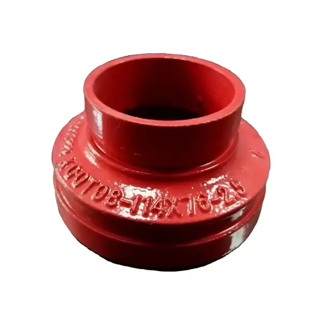
Ductile iron concentric reducers are flanged fittings in which the centerlines of the inlet (larger) and outlet (smaller) bores coincide, creating a symmetrical, “bull-nose” profile that ensures uniform flow transition. They differ from eccentric reducers, which offset the smaller bore to one side to maintain top-or-bottom alignment in horizontal piping. Concentric reducers are ideal for vertical runs (pump suction, lift stations) and meter runs, where a centered bore avoids gauge misreads and air-pocket formation.
Manufactured as full-body castings, concentric reducers have flanges matching the larger nominal size’s drilling template, with the smaller bore machined into one end. This “full-face” design simplifies installation by eliminating separate adapters or weld necks. Common applications include transitions in potable-water mains, process-water lines, fire-sprinkler mains, and HVAC chilled-water loops.
2. Material Specifications and Applicable Standards
2.1 Ductile Iron Material (ASTM A536)
All concentric reducers in this article are cast from nodular (spheroidal) graphite ductile iron per ASTM A536 Grade 65-45-12, providing a minimum tensile strength of 65 000 psi, yield strength of 45 000 psi, and elongation of 12 %. The spheroidal graphite microstructure grants superior toughness, fatigue resistance, and impact strength versus grey cast iron, essential for buried mains and cyclic loading.
2.2 Flange Standards
-
ANSI/AWWA C110/A21.10: Governs dimensions, drilling, and tolerances for Class 125 (150 psi) and Class 250 (250 psi) ductile iron flanged fittings up to 64″.
-
ASME B16.1: Covers Class 125 and Class 250 cast iron flanges and flanged fittings, ensuring interchangeability with process-industry components.
-
ANSI B16.42: Sometimes referenced for ductile iron flanges beyond 12″ for higher pressure ratings (PN 16/275 psi).
Concentric reducers machined per these standards guarantee bolt-hole alignment and sealing face compatibility with mating flanges, mechanical joints, or slip-on and weld-neck adapters.
3. Dimensional Charts and Size Ranges
Concentric reducers are specified by two nominal sizes: the larger “run” size and the smaller “branch” size (e.g., 8″×6″). Below is a comprehensive table of center-to-face (L), overall length (OAL), flange OD, bolt-circle diameter, and weight for standard sizes 2″×1½″ through 12″×8″ (Class 125).
| Run × Branch (in) | Center-to-Face L (in) | OAL (in) | Flange OD (in) | Bolt-Circle Dia. (in) | No. Holes | Hole Dia. (in) | Weight (lbs) |
|---|---|---|---|---|---|---|---|
| 2 × 1½ | 5.50 | 6.25 | 6.00 | 4.75 | 4 | 0.62 | 18 |
| 3 × 2 | 6.50 | 7.25 | 7.50 | 6.00 | 4 | 0.75 | 32 |
| 4 × 3 | 7.50 | 8.25 | 9.00 | 7.50 | 8 | 0.75 | 48 |
| 6 × 4 | 9.50 | 10.25 | 11.00 | 9.50 | 8 | 0.88 | 72 |
| 8 × 6 | 11.00 | 12.00 | 13.50 | 12.00 | 8 | 0.88 | 110 |
| 10 × 8 | 12.50 | 13.50 | 15.50 | 14.00 | 8 | 0.88 | 165 |
| 12 × 8 | 14.00 | 15.25 | 17.50 | 16.00 | 8 | 0.88 | 210 |
Table 1: Class 125 Concentric Reducer Dimensions and Weights
Larger sizes (14″×12″ through 64″×48″) follow identical flange drilling but have increased face-to-face lengths and weights, typically available on special order for 16″×14″ (230 lbs), 24″×18″ (645 lbs), and up to 64″×48″ (1 585 lbs).
4. Pressure Ratings and Hydraulic Performance
4.1 Pressure Classes
-
Class 125 (150 psi): Standard for potable-water and fire-protection systems; suitable for working pressures up to 150 psi at ambient temperature.
-
Class 250 (250 psi): Optional for higher-pressure industrial or raw-water services; drilling pattern differs (larger bolt holes/bolt circle) and is non-interchangeable with Class 125.
-
PN 16 (275 psi): Rarely applied, per ANSI B16.42 for very-large diameters (>12″) in specialized services.
4.2 Hydraulic Characteristics
The smooth, tapered interior of concentric reducers minimizes turbulence and pressure drop. According to Crane Technical Paper 410, the head loss coefficient for a 2:1 concentric reduction is approximately 0.20–0.30, significantly lower than comparable eccentric fittings due to symmetrical flow entry.
5. Types and Variations of Concentric Reducers
5.1 Full-Body Flanged Reducers
Solid, one-piece castings with full flange thickness matching the larger size. Machined to final bore on the smaller end; available only in Class 125 or Class 250 drilling patterns.
5.2 SWG & CWSG (Grooved) Reducers
Supplied with grooved ends per ANSI/AWWA C606, enabling coupling with Victaulic-style mechanical couplings; center-to-face and OD dimensions conform to C110 for drilling, but wall thickness per C153 for grooved fittings.
5.3 Mechanical Joint Concentric Reducers
Feature MJ glands and rubber gaskets per ANSI/AWWA C111/A21.11, rated to 350 psi for 3″–24″ and 250 psi for 30″–48″. Provide a bolted, gasketed connection without flanges.
6. Manufacturing Process and Quality Control
-
Pattern & Mold Making
– Machined wooden or resin patterns sized per ANSI/AWWA templates. -
Casting
– Sand-casting ductile iron at ~2 800 °F, followed by slow cooling to achieve nodularity. -
Heat Treatment
– Annealing cycle to spheroidize graphite and relieve stresses, meeting ASTM A536 mechanical properties. -
Machining
– CNC face-to-face milling, bore reaming, flange drilling per Class 125/250 templates. -
Inspection & Testing
– Dimensional inspection with CMM; hydrostatic test per AWWA standards; magnetic particle or ultrasonic testing for casting defects. -
Coating
– Interior cement-mortar lining (ANSI/AWWA C104/A21.4) and exterior primer (asphaltic or epoxy) per SSPC-SP standards.
7. Installation, Testing & Maintenance
7.1 Installation Best Practices
-
Align bolt holes by rotating the full-body reducer flange, avoiding pipe rotation.
-
Use ASTM A307 Grade B or F593 stainless bolts torqued in star pattern to 70–120 ft-lb (Class 125).
-
Install EPDM or nitrile gaskets rated for service temperature and pressure; full-face gaskets are recommended for corrosion protection.
7.2 Testing
-
After installation, perform hydrostatic or pneumatic testing at 1.5× working pressure (per AWWA C600), monitoring for leaks.
-
Flush piping to remove debris and verify flow characteristics.
7.3 Maintenance
-
Periodic inspection of flange coating integrity; recoat damaged areas.
-
Check bolt torque every 6–12 months, retightening per manufacturer specs.
-
Replace gaskets upon removal; inspect bores for corrosion or wear.
8. Corrosion Protection and Coatings
-
Internal Lining: Cement-mortar per ANSI/AWWA C104/A21.4; thickness 0.01–0.03 in.
-
External Coating:
-
Asphaltic primer (100–150 μm) per AWWA C110.
-
Epoxy (250–500 μm) for aggressive soils.
-
-
Cathodic Protection:
-
Sacrificial zinc anodes attached near reducers in buried mains.
-
Impressed-current systems for large-diameter, high-pour point soils.
-
9. Pricing Factors and Cost Comparison
| Factor | Impact on Cost |
|---|---|
| Nominal Size | Material volume and machining time increase roughly with diameter² |
| Pressure Class | Class 250 drilling adds 15–25% over Class 125 due to larger bolt circle |
| Coating Type | Epoxy adds ~20% to base casting; galvanizing adds 25–35% |
| Quantity/Lead Time | Bulk orders (>100 pcs) receive 10–15% discount; custom sizes incur tooling fees |
| Certification & Testing | Third-party certification (WRAS, NSF) and NDT add 5–10% |
Table 2: Key Pricing Drivers for Ductile Iron Concentric Reducers
Typical street prices (USD, Class 125, single piece):
| Run × Branch | Price Range ($) |
|---|---|
| 4″ × 3″ | 85–110 |
| 6″ × 4″ | 130–165 |
| 8″ × 6″ | 210–260 |
| 12″ × 8″ | 430–520 |
10. Market Availability & Leading Suppliers
-
McWane Ductile (Clow Valve): Full C110/Grooved/SWG lineup 2″–64″; robust US inventory.
-
American Cast Iron (American-USA): Offers ANSI/AWWA C110 and C153 reducers 2″–12″ with cement lining and asphaltic coating.
-
EJP Cooper-Ring: Stocks MJ and flanged reducers 3″–24″ with rapid dispatch; epoxy and galvanizing options.
-
Victaulic: Grooved concentric reducers per C110/C153; worldwide distribution.
Six Commonly Asked Questions (FAQs)
FAQ 1: How do I choose between concentric and eccentric reducers?
Choosing concentric versus eccentric reducers depends on piping alignment and air-pocket prevention. Concentric reducers maintain a common centerline, ideal for vertical drops, pump suctions, and meter runs where any offset could trap air or cause misalignment in instruments. Eccentric reducers, which offset the smaller bore to the top (or bottom), are used in horizontal mains to maintain full-drain slope and avoid gas pockets beneath the reducer when installed with the flat side up.
When specifying, consider:
-
Flow characteristics: Concentric offers symmetrical flow, minimizing head loss (K≈0.20–0.30 per Crane TP 410).
-
Installation orientation: Horizontal lines with slope require eccentric reducers flat-side up.
-
Instrumentation: Pumps and meters calibrated for centered flow require concentric fitting.
-
Space constraints: Eccentric may reduce vertical clearance by shifting centerline.
FAQ 2: Can concentric reducers be used in high-temperature applications?
While ductile iron is typically rated for ambient to 150 °F in water systems, concentric reducers with Class 125 drilling can be used up to ~225 °F in non-potable services when fitted with appropriate gaskets (e.g., non-asbestos compressed fiber rated to 300 °F). Above this, consider steel weld-neck reducers per ASME B16.5 for temperatures >350 °F to avoid creep and gasket extrusion. Corrosion-resistant alloys (e.g., Hastelloy-lined) may be specified for aggressive fluids.
FAQ 3: What torque values are recommended for flange bolts?
For Class 125 concentric reducers (ASTM A536), use ASTM A307 Grade B or F593 stainless bolts torqued to:
-
½″ bolts: 50–70 ft-lb
-
⅝″ bolts: 75–95 ft-lb
-
¾″ bolts: 100–125 ft-lb
Torque in a star pattern to ensure uniform gasket compression and avoid flange distortion.
FAQ 4: How does internal cement-mortar lining affect pressure capacity?
Cement-mortar lining per ANSI/AWWA C104/A21.4 provides corrosion protection and smooth hydraulic surfaces but slightly reduces internal diameter (<1 mm) and raises allowable stress temperatures (~212 °F). Lining thickness (0.01–0.03 in) does not compromise structural integrity; hydrostatic tests at 1.5× working pressure confirm leak-tight performance.
FAQ 5: Are concentric reducers compatible with mechanical joint fittings?
Yes. Mechanical joint (MJ) concentric reducers with MJ glands and rubber gaskets per ANSI/AWWA C111 are rated to 350 psi for 3″–24″ and 250 psi for 30″–48″. They mate directly with MJ pipes and accessories, offering rapid assembly without welding or flange bolts.
FAQ 6: What is the cost-benefit comparison between ductile iron and steel concentric reducers?
| Material | Cost ($/ea) | Installation Labor | Corrosion Protection | Life Cycle Cost |
|---|---|---|---|---|
| Ductile Iron | 20–30% less | Lower (bolted) | Standard lining | Lower (20–30 yrs) |
| Carbon Steel | Higher | Higher (welded) | Secondary lining | Higher (10–15 yrs) |
Ductile iron concentric reducers cost ~10–25 % less than carbon-steel weld-neck equivalents and bolt on quickly, avoiding welding labor and inspections. Cement-mortar lining is standard on ductile iron, whereas steel requires an extra coating, raising total installed cost by ~15–20 %.
References:
- ASTM A536 – Standard Specification for Ductile Iron Castings
- ANSI/AWWA C110/A21.10 – Ductile-Iron and Gray-Iron Fittings for Water
- ASME B16.1 – Cast Iron Pipe Flanges and Flanged Fittings
- Wikipedia – Ductile Iron Pipe Overview
- Crane Technical Paper 410 – Flow of Fluids Through Valves, Fittings & Pipe
