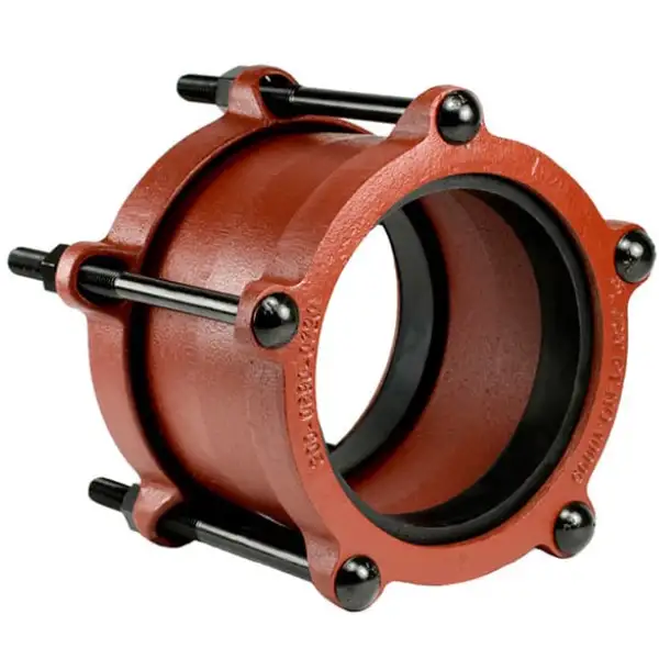
Ductile iron bolted (sleeve-type) couplings—per ANSI/AWWA C219 and ISO 2531—are versatile mechanical joints used to connect plain-end pipe in waterworks, wastewater, and industrial systems. They consist of two ductile iron housing halves, an elastomeric gasket, bolts/nuts, and end rings. Key advantages include fast installation, allowance for misalignment, vibration damping, and high pressure ratings (up to 16 bar for standard designs).
I. Definitions & Components
Ductile iron bolted couplings (aka sleeve-type couplings) join plain-end pipes without welding or flanges. They comprise:
-
Housing Halves: Two precision-machined ductile iron castings that bolt together around the pipe.
-
Elastomeric Gasket: EPDM, NBR, or FKM material seated in the coupling bore, providing a leak-tight seal under pressure and allowing limited movement.
-
Bolts & Nuts: Typically Grade A307 or ASTM A193/B7 steel, sized per coupling diameter.
-
End Rings (optional): For transition or reducing couplings, interchangeable end rings accommodate different pipe OD ranges.
Together, these elements form a mechanical compression joint that seals under internal pressure while allowing axial, lateral, and angular misalignment.
II. Material Properties & Gasket Design
Ductile Iron Characteristics
-
Grade: ASTM A536 65-45-12 provides ≥ 65 ksi tensile strength and ≥ 12% elongation, ensuring high ductility under stress.
-
Microstructure: Spheroidal graphite nodules minimize crack initiation, improving impact resistance over gray iron.
-
Corrosion Resistance: Base ductile iron may be fusion-bonded epoxy coated internally and externally for potable water service.
Gasket Materials
| Material | Service Range | Key Properties |
|---|---|---|
| EPDM | −30 °C to +110 °C | Excellent water/steam resistance |
| NBR | −20 °C to +80 °C | Good oil/fuel resistance |
| FKM | −20 °C to +200 °C | High-temp/chemical resistance |
Elastomer selection depends on fluid compatibility, temperature, and pressure. For potable water, EPDM is standard; for hydrocarbons, NBR or Viton (FKM) is preferred.
III. International Standards & Certifications
| Standard | Region | Scope |
|---|---|---|
| AWWA C219 | USA | Bolted, sleeve-type couplings for plain-end pipe, sizes ½″–144″, pressures up to 16 bar. |
| EN 545 / ISO 2531 Annex E | Europe / Intl. | Mechanical couplings for ductile iron pipelines, DN 40–DN 2600, with test methods and materials. |
| JIS B2311 | Japan | Bolted joint couplings for ductile iron pipe systems. |
| NSF 61 | USA | Certification for potable water components. |
Meeting these standards ensures dimensional interchangeability, performance consistency, and regulatory compliance across global projects.
IV. Dimensions & Sizing Chart
Below is a representative excerpt covering the most common sizes (1″–12″). Manufacturers may offer extended ranges (up to 144″ as per AWWA C219).
| Nominal Size | Pipe OD (mm) | Coupling Length L (mm) | Bolt Size & Qty. | Max Pressure (bar) |
|---|---|---|---|---|
| 1″ | 33.7 | 90 | M12 × 4 | 16 |
| 2″ | 60.3 | 110 | M16 × 4 | 16 |
| 4″ | 114.3 | 140 | M20 × 6 | 16 |
| 6″ | 168.3 | 170 | M24 × 6 | 16 |
| 8″ | 219.1 | 200 | M24 × 6 | 10 |
| 12″ | 323.9 | 260 | M27 × 8 | 10 |
Table 1. Standard ductile iron bolted coupling dimensions and pressure ratings.
For 14″–144″ sizes, refer to AWWA C219 Annex A and manufacturer catalogs.
V. Installation & Torque Procedures
Correct installation ensures leak-free service and coupling longevity:
-
Surface Preparation:
-
Remove burrs, paint, or scale on pipe ends.
-
Wipe gasket seating area clean.
-
-
Gasket Placement:
-
Center gasket on pipe OD; confirm full contact, no folds.
-
-
Assemble Housing Halves:
-
Engage lugs, ensure alignment of bolt holes.
-
-
Bolt-Up Sequence:
-
Step 1: Finger-tighten all bolts in star pattern.
-
Step 2: Torque to 30% of specified value.
-
Step 3: Torque to 60%.
-
Step 4: Torque to 100%; repeat once to accommodate gasket creep.
-
-
Inspection & Testing:
-
Hydrostatic test at 1.25× design pressure.
-
Visual leak check under operating conditions.
-
Always follow the coupling manufacturer’s torque charts—over-torquing can damage gaskets; under-torquing leads to leaks.
VI. Performance Comparison
| Feature | Bolted Coupling | Flanged Joint | Welded Joint |
|---|---|---|---|
| Installation Time | < 30 min | Several hours | > 4 h (incl. NDT) |
| Flexibility | High | Low | None |
| Misalignment | ± 3 mm axial, ± 2° angular | ± 0.5 mm | None |
| Pressure Rating | Up to 16 bar | Up to 25 bar | System rating |
| Cost per Joint | Low–Medium | High | High |
| Maintenance Ease | Simple gasket swap | Bolt retorque | Cutting weld |
Bolted couplings excel in fast repairs, retrofit jobs, and systems subject to thermal expansion or vibration, whereas flanges and welds suit ultra-high pressure or critical services.
VII. Selection Criteria & Sizing Workflow
-
Service Conditions:
-
Fluid type, temperature, pressure, external environment (soil, UV).
-
-
Material & Coatings:
-
Ductile iron body with epoxy or fusion-bonded coatings for corrosion protection.
-
Select gasket (EPDM, NBR, FKM) per compatibility.
-
-
Pressure Rating & Safety Factor:
-
Choose couplings rated ≥ 1.5× design pressure.
-
-
Misalignment & Movement:
-
Use flexible couplings when axial/thermal movement expected.
-
-
Accessory Requirements:
-
End rings for reducing/transition joints; restraint kits for thrust blocking.
-
-
Dimensional Check:
-
Confirm pipe OD matches coupling bore and end ring tolerances.
-
-
Quality Assurance:
-
Inspect certifications (AWWA, ISO, NSF) and factory test reports.
-
Following this workflow ensures the correct coupling is specified, avoiding field modifications and project delays.
VIII. Maintenance & Troubleshooting
-
Routine Inspection (Annually):
-
Check bolt tightness; re-torque to spec as needed.
-
Inspect gasket for extrusion or aging; replace if deformed.
-
-
Leak Diagnosis:
-
Visual: Drips or seepage at joint.
-
Pressure Decay Test: Isolate segment, pressurize at 1.25× working pressure, monitor drop.
-
Ultrasonic Leak Detection: Identify micro-leaks under pressure.
-
-
Coating Integrity:
-
Examine external epoxy or galvanizing for damage; touch-up per manufacturer guidelines.
-
-
Gasket Replacement Cycle:
-
Every 5–10 years in potable water; sooner in aggressive fluids.
-
Prompt maintenance prevents unscheduled shutdowns and extends coupling life well beyond 20 years.
IX. Cost Analysis & Lifecycle Considerations
| Cost Element | Bolted Coupling | Flanged Joint | Welded Joint |
|---|---|---|---|
| Material | $10–$50 | $100–$300 | $150–$400 |
| Installation Labor | Low | Medium | High |
| Routine Maintenance | Low | Medium | High |
| Replacement Cycle | 10–15 years | 20 years | 30 years |
While flanges and welds may offer slightly longer service intervals, the rapid install and lower labor of bolted couplings often yield lower total cost of ownership in small to medium mains and repair works.
YouTube Video Tutorial
*Practical demonstration of ductile iron bolted coupling installation and torque procedure.*
Common Questions
1. What tolerances do bolted couplings allow for pipe misalignment?
Mechanical bolted couplings are designed with elastomeric gaskets and segmented housings that accommodate axial, lateral, and angular misalignment. Standard couplings typically allow ± 3 mm lateral displacement and ± 2° angular deflection per joint, while flexible couplings extend lateral tolerance to ± 5 mm and angular to ± 3°. This flexibility arises from the gasket’s ability to deform elastically within the coupling bore, maintaining a seal even when pipe ends are not perfectly aligned. In field installations—especially on aged infrastructure where pipe straightness cannot be guaranteed—this tolerance removes the need for precision centering or costly pipe cutting and shimming. For dynamic systems subject to thermal expansion, vibration, or settlement, flexible couplings prevent undue stress on pipelines and connected equipment. Restrained coupling variants include shear keys or lock-ring inserts that engage the pipe exterior, providing both sealing flexibility and axial thrust resistance at dead-ends, bends, or valve locations. By choosing the appropriate coupling type (standard vs. flexible vs. restrained), engineers can accommodate alignment variances up to industry-specified limits, simplifying installation and enhancing long-term joint reliability.
2. Can bolted ductile iron couplings be used for natural gas service?
Yes—when both coupling and gasket materials are gas-rated and installation complies with relevant gas codes (e.g., ISO 14236, EN 1555, local regulations). Key considerations:
-
Body Material: Ductile iron per ASTM A536 or ISO 2531; optionally fusion-epoxy coated for corrosion protection.
-
Gasket: Gas-approved elastomer (e.g., NBR with low gas permeability), subject to EN 682 testing.
-
Pressure Testing: Each joint must pass a bubble or pressure decay test at ≥ 1.5× operating pressure.
-
Bolt Tightness: Torqued precisely to avoid creep-induced leaks; re-torque after 24 h.
-
Certifications: Couplings should bear CE or ANSI markings for gas service.
Natural gas systems demand absolute tightness; accordingly, manufacturers produce gas-specific coupling lines with tighter dimensional tolerances and lower allowable leak rates. Always enlist a qualified gas-system installer and adhere to all safety protocols.
3. What distinguishes restrained mechanical couplings from standard types?
Standard (unrestrained) couplings rely solely on gasket compression for sealing and do not resist axial pipe movement under internal pressure. Conversely, restrained couplings integrate mechanical features—shear lugs, wedge rings, or lock-rings—that clamp onto the pipe exterior, providing axial thrust resistance equal to the coupling’s rated pressure. Benefits include:
-
Elimination of concrete thrust blocks at dead-ends, tees, or bends.
-
Compact installation footprint, especially in congested valve chambers.
-
Simplified assembly, as the same coupling body can serve both sealing and restraint functions (depending on installed inserts).
Restrained designs must be specified where internal pressure generates unbalanced forces—e.g., at closed-valve ends or direction changes—to prevent joint separation and pipe pull-out.
4. How do environmental conditions affect coupling selection and lifespan?
Service environment drives material and coating choices, influencing inspection intervals and expected service life:
-
Corrosive Soils/Water: Require external coatings—galvanizing (≥ 86 µm Zn) or fusion-bonded epoxy—and use of stainless steel bolts to prevent galvanic corrosion.
-
UV & Ozone Exposure: Select gasket compounds with UV resistance (EPDM over NBR) for above-ground applications.
-
Temperature Extremes:
-
Low: Ensure gaskets remain flexible to −30 °C.
-
High: EPDM (≤ 110 °C), FKM (≤ 200 °C).
-
-
Chemical Exposure: In aggressive chemical service, FKM or specialty elastomers resist swelling; consider duplex coatings on housing.
In aggressive conditions, plan for more frequent inspections (semi-annual) and gasket replacements (every 5 years) to preempt leaks.
5. Are there significant dimension variations among manufacturers?
Standards ensure bolt patterns and pressure classes match, but minor dimensional variations exist:
-
Coupling Length (L): ± 10 mm between brands.
-
Bolt Diameter & Grade: Ranges from M16–M27; Grade 8.8 or B7.
-
End Ring Profiles: Some use converging gasket seats; others rectangular.
-
Gasket Cross-Section: Varies to optimize seal vs. ease of installation.
To avoid field mismatches, always verify the exact coupling OD, gasket part number, and bolt specification from the chosen supplier’s catalog and, if possible, request CAD drawings for clash detection in tight installs.
References:
- American Water Works Association (AWWA) Standards – Official Site
- ISO 2531: Ductile Iron Pipes, Fittings, Accessories and Their Joints — International Organization for Standardization
- Ductile Iron — Wikipedia
- NSF/ANSI 61 – Drinking Water System Components – Health Effects (NSF International)
- ASTM A536 – Standard Specification for Ductile Iron Castings
