Ductile iron flanged spools are prefabricated lengths of ductile iron pipe with one or two integrally cast flanged ends. They provide flexibility during installation—allowing easy mating to valves, fittings, and equipment—while maintaining the strength and corrosion resistance that make ductile iron the industry standard for water, wastewater, fire protection, and industrial process pipelines.
Key Takeaways:
-
Size Versatility: Spools are available from DN 50 (2″) to DN 1200 (48″) in lengths from 1 ft to 20 ft, with precise dimensional tolerances to ensure interchangeability.
-
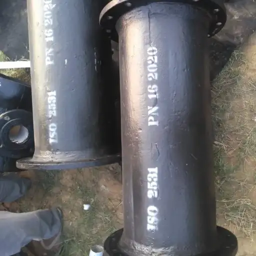
Standards Compliance: Manufactured per ANSI/AWWA C115/A21.15 for threaded-on flanges and C110/C153 for integrally cast spools, and with EN 1092-2 / ISO 2531 for global markets.
-
Pressure Ratings: Commonly rated 150 psi (Class 150), 250 psi, or 300 psi, with PN16 and PN25 metric equivalents—bolting patterns differ significantly between ANSI and PN standards.
-
Installation Best Practices: Proper trench bedding, flange alignment, gasket selection, and bolt-torque sequencing are critical for leak-free service.
-
Corrosion Protection: External bituminous or epoxy coatings, plus internal cement mortar or epoxy linings, extend service life in aggressive soils or fluids.
Section 1: Overview & Standards
1.1 What Is a Flanged Spool?
A flanged spool (also called a flanged connecting piece) is a prefabricated ductile iron pipe segment with one or two flanged ends. It eliminates the need to field-weld or bolt loose flanges onto pipe, reducing installation time and ensuring factory-controlled dimensional accuracy.
1.2 Materials & Ductile Iron Grades
Flanged spools are cast from ductile iron conforming to ASTM A536 Grade 65-45-12, offering a minimum tensile strength of 65 ksi and 45 ft-lb impact toughness at – 30 °C, with nodular graphite microstructure for excellent ductility and fatigue resistance.
1.3 Applicable Standards
-
ANSI/AWWA C115/A21.15: Specifies threaded flange ends and flange dimensions for spools up to Class 250 psi.
-
ANSI/AWWA C110/A21.10: Governs integrally cast flanged fittings (Class 150–250 psi) with longer face-to-face lengths.
-
ANSI/AWWA C153/A21.53: Covers compact, integrally cast Class 350 psi spools with reduced face-to-face dimensions.
-
EN 1092-2 (PN10–PN25) & ISO 2531/7186: European and international equivalents, defining metric bolt patterns, face types, and tolerance requirements for global interoperability.
Manufacturers often maintain dual compliance (AWWA + EN/ISO) and third-party certification (e.g., WRAS, DVGW) to serve both North American and international markets.
2. Spool Size Ranges & Dimensions
Ductile iron flanged spools are available in nominal pipe sizes from DN 50 (2″) up to DN 1600 (64″) to accommodate most water, wastewater, fire-protection, and industrial piping systems. Spools typically come in factory-fabricated lengths from 1 ft (0.3 m) up to 20 ft (6 m), with longer lengths custom-fabricated on request. The minimum and maximum standard lengths for common sizes (2″–12″) are published in manufacturer catalogs; for example, 3″–8″ spools range from 1 ft to 19 ft 6 in, while 10″–12″ spools range from 1 ft to 15 ft 6 in.
Dimensional tolerances on outside diameter (OD) and face-to-face length follow AWWA C110/A21.10 and ANSI B16.1:
-
OD Tolerance: ±0.05 in (2″–8″), ±0.06 in (10″–12″), increasing for larger sizes.
-
Face-to-Face Length Tolerance: ±0.06 in for all listed sizes to ensure interchangeability.
Table 2-1: Typical Flanged Spool Dimensions
| Nominal Size (in) | Nominal Size (DN) | OD (in) | Min Length (ft) | Max Length (ft) | Tolerance (±in) |
|---|---|---|---|---|---|
| 2″ | 50 | 2.375 | 1 | 20 | 0.05 |
| 4″ | 100 | 4.500 | 1 | 19.5 | 0.05 |
| 6″ | 150 | 6.625 | 1 | 19.5 | 0.05 |
| 8″ | 200 | 8.625 | 1 | 19.5 | 0.05 |
| 10″ | 250 | 10.750 | 1 | 15.5 | 0.06 |
| 12″ | 300 | 12.750 | 1 | 15.5 | 0.06 |
| 16″ | 400 | 16.000 | 1 | 12 | 0.07 |
| 24″ | 600 | 24.000 | 1 | 10 | 0.07 |
Data adapted from U.S. Pipe and AMERICAN catalogs.
3. Flange Drilling Patterns & Pressure Ratings
Flanged spools utilize drilled flange faces per ANSI/AWWA C110 or EN 1092-2, with bolt-hole patterns keyed to pressure class. ANSI Class 150 (≈150 psi) and Class 300 (≈300 psi) correspond to PN16 and PN25 metric ratings, respectively.
-
ANSI/AWWA C110 Class 150: Bolt circle and hole pattern per ANSI B16.1; e.g., a 6″ flange uses eight 3⁄4″ holes on a 9.50″ bolt circle.
-
ANSI B16.42 Class 300: Heavier drilling—larger bolt circle and more bolts—to withstand 300 psi; for 6″, eight 7⁄8″ holes on a 10.88″ bolt circle.
-
EN 1092-2 PN16: Metric drill pattern—e.g., DN 150 uses eight M16 holes on a 225 mm bolt circle; flange face is usually flat (FF) with full-face gasket.
-
EN 1092-2 PN25: Similar layout to PN16 but with M20 holes on a 241 mm bolt circle; thicker flange thickness to handle 25 bar (≈362 psi).
Table 3-1: Flange Drilling Patterns by Size & Class
| Nominal Size | Class 150 (ANSI) | Class 300 (ANSI) | PN16 (EN) | PN25 (EN) |
|---|---|---|---|---|
| 4″ | 4×¾″ holes @ 7.50″ BC | 4×7⁄8″ @ 8.50″ BC | 4×M16 @ 165 mm BC | 4×M20 @ 185 mm BC |
| 6″ | 8×¾″ @ 9.50″ BC | 8×7⁄8″ @ 10.88″ BC | 8×M16 @ 225 mm BC | 8×M20 @ 241 mm BC |
| 8″ | 8×¾″ @ 11.00″ BC | 8×7⁄8″ @ 12.88″ BC | 8×M16 @ 285 mm BC | 8×M20 @ 301 mm BC |
| 12″ | 8×¾″ @ 13.50″ BC | 8×7⁄8″ @ 15.50″ BC | 8×M16 @ 340 mm BC | 8×M20 @ 355 mm BC |
BC = bolt circle diameter. Data compiled from McWane and U.S. Pipe technical bulletins.
4. Connection Types & Jointing Methods
Ductile iron flanged spools may terminate in a variety of connection types to interface with pipe, fittings, or equipment:
4.1 Flange × Plain End (PE)
One end is flanged per ANSI/AWWA C110 or C115; the opposite end is plain-end to suit push-on joints (Tyton®) or mechanical joints. This hybrid spool simplifies transitions from flanged valves to buried push-on mains.
4.2 Flange × Mechanical Joint (MJ)
One end has an integrally cast flange while the other end is prepared with MJ socket, gland, and gasket per AWWA C111. MJ spools are common for buried water mains requiring deflection and easy maintenance.
4.3 Flange × Flange (FF)
Both ends are flanged—ideal for above-ground piping, pump connections, and fire protection headers. FF spools ensure maximum alignment control and ease of disassembly.
4.4 Threaded-On Flanges (C115)
For smaller sizes (2″–6″), loose flanges of ANSI B16.1 can be threaded onto pipe ends per AWWA C115; suitable when mating to threaded valves or equipment. This method avoids welding but is not recommended for buried services due to potential thread corrosion.
5. Installation Best Practices
Proper installation of ductile iron flanged spools is essential to ensure leak-free service and long-term reliability.
-
Trench Preparation & Bedding
Excavate trench according to AWWA C600, providing a uniform bed of granular material (sand or pea gravel) at least 4 in (100 mm) thick under the pipe.
The trench should be wide enough (pipe OD + 24 in) to allow workers to place and compact bedding without disturbing the pipe.
Side fill must be placed in layers ≤ 6 in and compacted to at least 90 % Standard Proctor density to prevent point loading on the pipe. -
Flange Alignment
Use flange spreaders and drift pins to align bolt holes precisely, avoiding misalignment that can stress flange faces and gaskets.
Check face-to-face distance per ANSI/AWWA C110 tolerances (± 0.06 in) to confirm spool length before bolting. -
Gasket Selection & Installation
Select gasket material based on service: EPDM for potable water (– 40 °C to + 120 °C), NBR for oils (– 30 °C to + 100 °C), and PTFE for chemicals (– 200 °C to + 260 °C).
Inspect gaskets for damage; center them on the flange face and apply a light coat of approved lubricant (e.g., silicone grease) to prevent pinching and ensure uniform compression. -
Bolt Selection & Lubrication
Use high-strength bolts (ASTM A193 Grade B7 or A307 Grade B) sized per ANSI B16.1 or EN 1092-2 tables, matching drilled holes (e.g., ¾″ bolts for Class 150, M16 for PN16).
Apply anti-seize or molybdenum-disulfide lubricant to threads and under bolt heads to achieve accurate torque and prevent galling. -
Torque Sequencing
Tighten bolts in a star (crisscross) pattern in three stages: 30 % of final torque, then 60 %, then 100 %.
For a ¾″ bolt, typical torque is 150–175 Nm; for an M16 bolt, 200–220 Nm—but always follow gasket manufacturer’s recommendations. -
Hydrostatic Testing & Retorque
After assembly, perform a hydrostatic test at 1.5 × design pressure (e.g., 150 psi × 1.5 = 225 psi) for at least 2 hours, per AWWA C600.
Following the test, retorque all bolts to 100 % of final torque after line is depressurized, then again after 24 hours to compensate for gasket creep.
6. Weight & Handling Considerations
Understanding the weight and safe handling of ductile iron flanged spools is vital for site logistics and safety planning.
-
Weight per Foot by Size & Class
Approximate weights (including flange) for ANSI Class 150 spools are: 4″ × 10 ft = 180 lb; 6″ × 10 ft = 320 lb; 8″ × 10 ft = 500 lb.
Class 300 spools of the same size weigh ~15 % more due to thicker walls (e.g., 6″ × 10 ft ≈ 370 lb). -
Lifting & Rigging
Use lifting lugs or slings rated for 2 × safety factor; avoid lifting by the flange alone to prevent damage to the flange face and bolt holes.
Position slings under the pipe barrel, clear of coating and gaskets; protect coating with padding to prevent abrasion. -
Safety Precautions
Require a minimum clearance zone of 2 m around hoisted loads; ensure all personnel are clear during lifting and placement.
Inspect slings, shackles, and spreader beams before each lift; tag equipment with inspection dates per OSHA 29 CFR 1910.184. -
Storage & Stacking
Store spools on level ground with wooden runners; do not stack more than three high to prevent tipping or coating damage.
Cover with breathable tarpaulin to protect from UV and moisture; maintain airflow to prevent condensation under the cover.
7. Coating, Lining & Corrosion Protection
Ductile iron flanged spools are protected internally and externally to resist corrosion in various environments:
-
External Coatings
-
Asphaltic (Bituminous) Coating: A thin, 1 mil seal coat applied per AWWA C151 protects against soil‐side corrosion and moisture ingress.
-
Polyethylene Encasement: A plastic wrap physically isolates the pipe from corrosive soils; often used in highly aggressive environments.
-
Epoxy & Fusion-Bonded Epoxy (FBE): Provide thicker, more impervious barriers; require sand‐blasted surface prep for adhesion; used where long service life (> 50 years) is required.
-
Polyurethane & Polyurea: Flexible, UV-resistant coatings for above-ground or splash zones; applied at 5–15 mils thickness.
-
-
Internal Linings
-
Cement Mortar (AWWA C104): Spin-applied ¼″ thickness; roughness coefficient C≈120; provides a durable barrier against potable-water corrosion.
-
Asphaltic Cement: Used where chemical resistance to hydrocarbons is needed; less common for potable water.
-
Epoxy: 0.01–0.02″ thick; smoother (C≈140), ideal for wastewater or chemically aggressive fluids; must meet NSF/ANSI 61 for potable systems.
-
-
Cathodic Protection
-
Sacrificial Anodes or Impressed Current Systems can be applied to highly corrosive soils; design per NACE SP0169 to maintain pipe potential below –0.85 V CSE.
-
8. Quality Control & Testing
Rigorous QC ensures each flanged spool meets performance requirements:
-
Hydrostatic Pressure Testing
Each spool is tested per AWWA C600 at 1.5× its rated pressure (e.g., Class 150 @ 150 psi, test @ 225 psi) for at least 2 hours to verify sealing integrity. -
Dimensional Inspection
OD, face‐to‐face length, bolt‐circle diameter, and bolt‐hole location tolerances are measured against ANSI/AWWA C110 and EN 1092-2 specifications (± 0.06″ for critical dimensions). -
Mechanical Testing
-
Tensile & Impact: Castings conform to ASTM A536 Grade 65-45-12, with ≥ 65 ksi tensile strength and ≥ 45 ft⋅lb Charpy V-Notch impact at –30 °C.
-
Hardness: Tested to 187–255 HB for correct matrix.
-
-
Non-Destructive Examination (NDE)
Ultrasonic thickness mapping and magnetic particle inspections detect subsurface flaws; critical for large‐diameter spools and high‐pressure classes. -
Coating & Lining Verification
Thickness measurements by mill and holiday testing ensure external and internal coatings meet specified mil-thickness and continuity standards.
9. Selection Guide & Application Examples
Choose the appropriate flanged spool based on service conditions, pressure, and lifecycle cost:
9.1 Municipal Water Distribution
-
Sizes: DN 100–DN 600 (4″–24″) common.
-
Class: PN16/C150 with cement mortar lining and asphaltic external coating.
-
Joint: Flange × Plain-End for transition to push-on mains.
9.2 Fire Protection
-
Sizes: DN 50–DN 300 (2″–12″).
-
Class: AWWA C153 Class 350 (350 psi) with epoxy lining; fire-rated EPDM gaskets.
-
Joint: Flange × Flange for pump and valve connections.
9.3 Industrial Process Piping
-
Chemicals: PTFE internal lining for aggressive fluids; FBE external for chemical plant environments.
-
Class: ANSI 300/PN25 for high‐pressure steam or hydraulic fluids.
-
Joint: Flange × Mechanical Joint where vibration isolation is needed.
9.4 Wastewater & Sewage
-
Size: DN 150–DN 1200 (6″–48″).
-
Class: PN10/C150 with bituminous lining; gaskets rated for effluent solids.
-
Joint: Flange × Plain-End to piggable push-on pipelines.
Comparison Table: Common Spool Sizes
| Nominal Size | OD (in/mm) | Length (ft/m) | Weight (lb/kg)* | Pressure Class |
|---|---|---|---|---|
| 4″ (DN 100) | 4.50 / 114 | 1–19.5 / 0.3–6 | 14 lb/ft (20 kg/m) (Class 150) | C150 / PN16 |
| 6″ (DN 150) | 6.90 / 175 | 1–19.5 / 0.3–6 | 22 lb/ft (33 kg/m) (C150); 25 lb/ft (38 kg/m) (C300) | C150, C300 / PN16, PN25 |
| 8″ (DN 200) | 9.05 / 230 | 1–19.5 / 0.3–6 | 31 lb/ft (46 kg/m) (C150); 36 lb/ft (54 kg/m) (C300) | C150, C300 / PN16, PN25 |
| 12″ (DN 300) | 13.20 / 335 | 1–15.5 / 0.3–4.7 | 51 lb/ft (76 kg/m) (C150); 58 lb/ft (87 kg/m) (C300) | C150, C300 / PN16, PN25 |
*Weights include flange; actual may vary by manufacturer.